
Service Manual


LINKAGE
4-11Floating Deck Mid-Size Service Manual
4
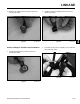
5. Remove the clevis pin and control linkage rod from
the drive lever assembly (Fig. 0331).
Fig 0331 PICT-0692
6. Remove the nut from the bolt securing the thumb
latch assembly to the handle bar (Fig. 0332).
4. Remove the hairpin cotter from the clevis pin retain-
ing the upper end of the control linkage to the drive
lever assembly (Fig. 0330).
Fig 0332 PICT-0694
Fig 0330 PICT-0691
7. Remove the bolt, spacer, washers and the thumb
latch assembly from the handle bar (Fig. 0333).
Fig 0333 PICT-0696