
Operator's Manual


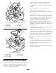


Figure40
1.Locknut
4.SpannerBushing
2.WheelBolt5.RollerBearing
3.Bushing
2.Removeonebushing,thenpullthespannerbushing
androllerbearingoutofthewheelhub(Figure40).
3.Removetheotherbushingfromthewheelhub
andcleananygreaseanddirtfromthewheelhub
(Figure40).
4.Inspecttherollerbearing,bushings,spannerbushing
andinsideofthewheelhubforwear.Replaceany
defectiveorwornparts(Figure40).
5.Toassemble,placeonebushingintothewheelhub.
Greasetherollerbearingandspannerbushingand
slidethemintothewheelhub.Placethesecond
bushingintothewheelhub(Figure40).
6.Installthecasterwheelintothecasterforkand
securewiththewheelboltandlocknut.Tightenthe
locknutuntilthespannerbushingbottomsagainst
theinsideofthecasterforks(Figure40).
7.Greasethettingonthecasterwheel.
AdjustingtheElectricClutch
Theclutchisadjustabletoensureproperengagement
andproperbraking.Checkadjustmentafterevery100
hoursofoperation.
1.Inserta0.015–0.021inch(0.381–0.533mm)feeler
gaugethroughoneinspectionslotinthesideofthe
assembly.Makesureitisbetweenthearmatureand
therotorfrictionsurfaces.
2.Tightenthelocknutsuntilthereisslightbindingon
thefeelergaugebutitcanbemovedeasilywithinthe
airgap(Figure41).
3.Repeatthisfortheremainingslots.
4.Checkeachslotagainandmakeslightadjustments
untilthefeelergaugebetweentherotorandarmature
withveryslightcontactbetweenthem.
Figure41
1.Adjustingnut3.Feelergauge
2.Slot
35