
Operator's Manual


FrameSetUp
CheckingtheCarrierFrameandEngine
DeckAlignment
Note:MisalignmentcancauseexcesswearonthePTO
drivebelt.
1.DisengagethePTOandsettheparkingbrake.
2.Stoptheengine,removethekey,andwaitforall
movingpartstostopbeforeleavingtheoperating
position.
3.Placealongstraightedgeontopoftheenginedeck
asshowninFigure69.
4.Atthecarrierframecrosschannel,measurethe
heightatlocationA(Figure69).Thismeasurement
mustbe1-5/16inch(33mm),plusorminusa1/4
inch(6mm).
5.IftheheightatlocationAisnotcorrect,adjustment
isneeded.
6.Loosenthecarrierframemountingboltsonboth
sidesofthemachine(Figure69).
7.Alignthecarrierframeandenginedecktomatch
1-5/16inch(33mm),plusorminusa1/4inch(6
mm)atlocationA(Figure69).
8.Tightenthecarrierframemountingboltsonboth
sidesofthemachine.
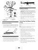
Figure69
1.CarrierFrame4.LocationA,1-5/16inch
(33mm)±1/4inch(6mm)
2.Topofenginedeck5.Straightedge
3.Carrierframemounting
bolts
6.Carrierframecross
channel
CheckingtheEngineDeckHeight
1.DisengagethePTOandsettheparkingbrake.
2.Stoptheengine,removethekey,andwaitforall
movingpartstostopbeforeleavingtheoperating
position.
3.Adjustthetirepressureinthe
reartirestospecications;referto
DriveSystemMaintenance(page33).
4.MeasureenginedeckheightatlocationA(Figure70).
5.MeasureenginedeckheightatlocationB(Figure70).
6.IftheheightatlocationAandBarenotthesame,
changetirepressureslightlytomakethemthesame.
Figure70
1.Backviewofmachine
3.Tires
2.Topofenginedeck4.Sameheightatlocations
AandB
CheckingtheCarrierFrame
Front-to-RearPitch
Thecarrierframemusthaveapitchbetween1/8inch
(3mm)to3/8inch(9mm)overthelengthof24inches
(61cm)onthecarrierframe(Figure71).
1.Measureout24inches(61cm)onthecarrierframe
(Figure71).
48