
Service Manual


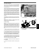

Table Of Contents
- Title Page
- Revision History
- Reader Comments
- Preface
- Table Of Contents
- 1 - Safety
- 2 - Product Records and Maintenance
- 3 - Kubota Diesel Engine
- Kubota 05 E2B Series Workshop Manual (S/N below 280000000)
- Kubota 05-E3B Series Workshop Manual (S/N 280000001 and up)
- Kubota 05-E4B Series Workshop Manual
- 4 - Hydraulic System
- Specifications
- General Information
- Hydraulic Schematics
- Hydraulic Flow Diagrams
- Special Tools
- Troubleshooting
- Testing
- Traction System Operation Testing
- Charge Relief Valve Pressure Test (Using Pressure Gauge)
- Transmission Piston Pump Flow Test (Using Tester with Pressure Gauges and Flow Meter)
- Traction Relief Valve Pressure Test (Using Tester with Pressure Gauges and Flow Meter)
- Wheel Motor Efficiency Test (Using Tester with Pressure Gauges and Flow Meter)
- PTO Pressure Valve Test (Using Pressure Gauge)
- Implement Relief Pressure Test (Using Pressure Gauge)
- Gear Pump Flow Test (Using Tester with Pressure Gauges and Flow Meter)
- Lift Cylinder Internal Leakage Test
- Service and Repairs
- General Precautions for Removing and Installing Hydraulic System Components
- Flush Hydraulic System
- Charge Hydraulic System
- Hydraulic Tank
- Wheel Motors
- Wheel Motor Service
- Transmission
- Transmission Service
- Gear Pump
- Gear Pump Service
- Manual Lift Control Valve (SN Below 313000000)
- Manual Lift Control Valve Service (SN Below 313000000)
- Lift Control Manifold (SN Above 313000000)
- Lift Control Manifold Service (SN Above 313000000)
- Polar TracTM Hydraulic Control Valve
- Polar TracTM Hydraulic Control Valve Service
- Lift Cylinder
- Lift Cylinder Service
- Polar TracTM Lift Cylinder
- Polar TracTM Lift Cylinder Service
- Oil Cooler
- Parker Torqmotor Service Procedure
- 5 - Electrical System
- Electrical Schematics and Diagrams
- Special Tools
- Troubleshooting
- Electrical System Quick Checks
- Component Testing
- Ignition Switch
- Indicator Lights
- Hour Meter
- PTO Switch
- Neutral Switches
- Seat Switch
- Parking Brake Switch (SN Below 310000000)
- Parking Brake Switch (SN Above 310000000)
- Standard Control Module
- Standard Control Module Logic Chart
- PTO Solenoid Valve Coil
- Lift Control Manifold Solenoid Valve Coils (SN Above 313000000)
- Fusible Link Harness
- Diode Assembly
- Glow Relay
- High Temperature Warning Switch
- High Temperature Shutdown Switch
- Dual Temperature Switch (Polar TracTM Machines)
- Deck Lift/Lower Switch (SN Above 313000000)
- Fuel Pump
- Fuel Stop Solenoid
- Glow Controller
- Service and Repairs
- 6 - Chassis
- 7 - Cutting Deck
- 8 - Foldout Diagrams
- Electrical Drawing Designations
- Hydraulic Schematics
- Hydraulic Schematic (SN Below 313000000)
- Hydraulic Schematic (SN Below 313000000) with Rear Attach Lift Kit
- Hydraulic Schematic (SN Below 313000000) with Polar Trac Installed)
- Hydraulic Schematic (SN Below 313000000) with Polar Trac and Rear Attach Lift Kit
- Hydraulic Schematic (SN From 313000001 to 314999999)
- Hydraulic Schematic (SN Above 315000000)
- Electrical Schematics
- Circuit Diagrams
- Wire Harness

Groundsmaster 7200/7210Page 5 - 24Electrical System
High Temperature Warning Switch
The high temperature warning switch is attached to the
water pump housing on the engine and has a yellow wire
attached to it (Fig. 30). This switch is normally open and
closes when engine coolant temperature reaches
approximately 220
o
F(105
o
C).
When engine coolant temperature rises to approximate-
ly 220
o
F(105
o
C), the high temperature warning switch
closes. T he closed switch causes the High Temperature
Warning Light on the console to illuminate and also pro-
vides an input to the Standard Control Module (SCM).
This input causes the SCM high temperature warning
LED to illuminate and the cutting deck (or implement) to
shut down. The temperature warning switch and circuit
wiring should be tested as a SCM input before perform-
ing the following testing procedure.
Testing
1. Parkmachineonalevelsurface, lower cutting deck
(or implement), stop engine, apply parking brake and re-
move key from ignition switch. Open hood to gain ac-
cess to engine.
CAUTION
Make sure engine is cool before removing the
temperature warning switch from engine. Do not
open radiator cap or drain coolant if the radiator
or engine is hot. Pressurized, hot coolant can es-
cape and cause burns.
2. Lower the coolant level in the engine, remove wire
harness connector from high temperature warning
switch and remove the switch from the engine.
3. Put the end of the switch in a container of oil with a
thermometer and slowly heat the oil (Fig. 31).
CAUTION
Handle the hot oil with extreme care to prevent
personal injury or fire.
NOTE: Prior to taking resistance readings with a digital
multimeter, short the meter test leads together. The me-
ter will display a small resistance value (usually 0.5
ohms or less). This resistance is due to the internal re-
sistance of the meter and test leads. Subtract this value
from from the measured value of the component you are
testing.
4. Checkresistanceofthewarningswitchwithamulti-
meter (ohms setting) as the temperature increases. The
high temperature warning switch is normally open and
should close from 216
o
to 226
o
F(102
o
to 108
o
C).
5. After testing, install warning switch to the engine
housing.
A. Clean threads of housing and switch thoroughly.
Apply thread sealant to the threads of the switch.
B. Thread warning switch into the housing. Torque
switch from 16 to 20 ft- lb (21.7 to 27.1 N- m).
C. Reconnect harness wire connector to warning
switch.
6. Fill engine cooling system.
7. Lower and secure hood.
1. High temperature warning switch
Figure 30
1
Figure 31