
Service Manual


Table Of Contents
- Title Page
- Revision History
- Reader Comments
- Preface
- Table Of Contents
- 1 - Safety
- 2 - Product Records and Maintenance
- 3 - Kubota Diesel Engine
- Kubota 05 E2B Series Workshop Manual (S/N below 280000000)
- Kubota 05-E3B Series Workshop Manual (S/N 280000001 and up)
- Kubota 05-E4B Series Workshop Manual
- 4 - Hydraulic System
- Specifications
- General Information
- Hydraulic Schematics
- Hydraulic Flow Diagrams
- Special Tools
- Troubleshooting
- Testing
- Traction System Operation Testing
- Charge Relief Valve Pressure Test (Using Pressure Gauge)
- Transmission Piston Pump Flow Test (Using Tester with Pressure Gauges and Flow Meter)
- Traction Relief Valve Pressure Test (Using Tester with Pressure Gauges and Flow Meter)
- Wheel Motor Efficiency Test (Using Tester with Pressure Gauges and Flow Meter)
- PTO Pressure Valve Test (Using Pressure Gauge)
- Implement Relief Pressure Test (Using Pressure Gauge)
- Gear Pump Flow Test (Using Tester with Pressure Gauges and Flow Meter)
- Lift Cylinder Internal Leakage Test
- Service and Repairs
- General Precautions for Removing and Installing Hydraulic System Components
- Flush Hydraulic System
- Charge Hydraulic System
- Hydraulic Tank
- Wheel Motors
- Wheel Motor Service
- Transmission
- Transmission Service
- Gear Pump
- Gear Pump Service
- Manual Lift Control Valve (SN Below 313000000)
- Manual Lift Control Valve Service (SN Below 313000000)
- Lift Control Manifold (SN Above 313000000)
- Lift Control Manifold Service (SN Above 313000000)
- Polar TracTM Hydraulic Control Valve
- Polar TracTM Hydraulic Control Valve Service
- Lift Cylinder
- Lift Cylinder Service
- Polar TracTM Lift Cylinder
- Polar TracTM Lift Cylinder Service
- Oil Cooler
- Parker Torqmotor Service Procedure
- 5 - Electrical System
- Electrical Schematics and Diagrams
- Special Tools
- Troubleshooting
- Electrical System Quick Checks
- Component Testing
- Ignition Switch
- Indicator Lights
- Hour Meter
- PTO Switch
- Neutral Switches
- Seat Switch
- Parking Brake Switch (SN Below 310000000)
- Parking Brake Switch (SN Above 310000000)
- Standard Control Module
- Standard Control Module Logic Chart
- PTO Solenoid Valve Coil
- Lift Control Manifold Solenoid Valve Coils (SN Above 313000000)
- Fusible Link Harness
- Diode Assembly
- Glow Relay
- High Temperature Warning Switch
- High Temperature Shutdown Switch
- Dual Temperature Switch (Polar TracTM Machines)
- Deck Lift/Lower Switch (SN Above 313000000)
- Fuel Pump
- Fuel Stop Solenoid
- Glow Controller
- Service and Repairs
- 6 - Chassis
- 7 - Cutting Deck
- 8 - Foldout Diagrams
- Electrical Drawing Designations
- Hydraulic Schematics
- Hydraulic Schematic (SN Below 313000000)
- Hydraulic Schematic (SN Below 313000000) with Rear Attach Lift Kit
- Hydraulic Schematic (SN Below 313000000) with Polar Trac Installed)
- Hydraulic Schematic (SN Below 313000000) with Polar Trac and Rear Attach Lift Kit
- Hydraulic Schematic (SN From 313000001 to 314999999)
- Hydraulic Schematic (SN Above 315000000)
- Electrical Schematics
- Circuit Diagrams
- Wire Harness
Rev. A
Groundsmaster 7200/7210Hydraulic System Page 4 - 86
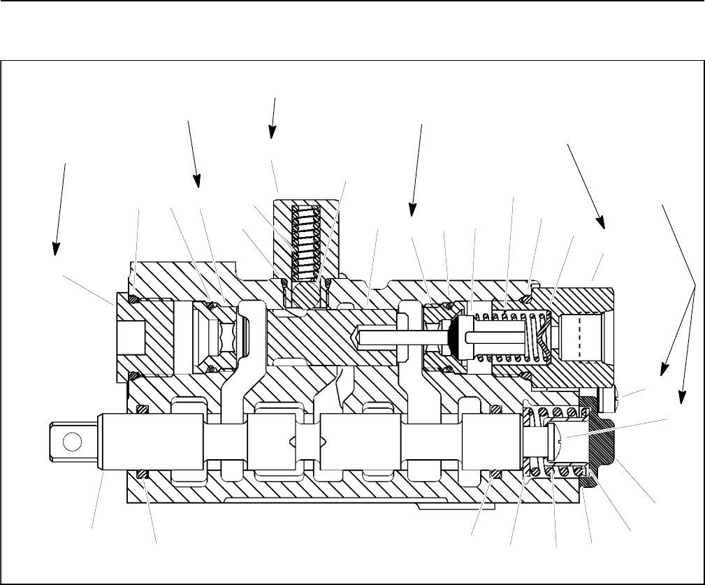
Manual Lift Control Valve Service (Serial Number Below 313000000)
1. Detent ball
2. Spring
3. Gasket
4. O- ring
5. Screw
6. Washer
7. Screw and lock washer (2 used)
8. Spool
9. Plug
10. Poppet stop
11. Poppet
12. End cap
13. Spacer
14. Adapter plug
15. O- ring
16. Detent plug
17. Spring
18. O- ring
19. Detent plunger
20. Spring
21. O- ring
22. Lockout seat
23. O- ring
Figure 101
10
12
13
14
11
8
9
7
6
4
2
1
3
5
4
15
16
17
18
19
20
22
23
21
23
22
35 to 40 ft- lb
(47to54N-m)
24 to 36 in- lb
(2.7 to 4.1 N- m)
18 to 20 ft- lb
(24to27N-m)
35 to 40 ft- lb
(47to54N-m)
10 to 15 ft- lb
(14to20N-m)
Loctite #242
Loctite #242
18 to 20 ft- lb
(24to27N-m)
Loctite #242
Disassembly (Fig. 101)
1. Plug all ports and clean the outside of control valve
thoroughly.
2. Remove two (2) screws with lock washers (item 7)
that secure end cap (item 12) to control valve. Remove
end cap.
3. Retain spool to prevent it f rom turning. Remove
screw (item 5), spacer (item 13), spring (item 20) and
washer (item 6) from control valve.
4. Carefully slide spool (item 8) from housing bore.
5. Carefully remove O- rings (item 4) from spool bore.
Take care to not damage spool bore or O- ring cavities
during O- ring removal.
6. Remove detent plug (item 16), O- ring (item 18),
spring (item 17) and detent ball (item 1).
7. Remove plug (item 9) with O- ring (item 21) and lock-
out seat (item 22) with O- ring (item 23) from valve body.
8. Remove adapter plug (item 14) with O- ring (item
15), poppet stop ( item 10), spring (item 2) and poppet
(item 11) from control valve body.