
Operator's Manual


Important:Thecurvedpartoftheblademust
bepointingupwardtowardtheinsideofthe
mowertoensurepropercutting.
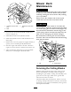
2.Installtheanti-scalpplateandbladebolt(
Figure77).
Figure77
1.Spindle
3.Anti-scalpplate
2.SailAreaofBlade
4.BladeBolt
3.Torquethebladeboltto85-110ft-lb(115-150N⋅m).
CorrectingMowerDeck
Mismatch
Ifthecutisunevenacrossthemowerswath,correct
itasfollows:
1.Positionthemachineonalevelsurfaceontheshop
oor.
2.Setthecuttingunittothedesiredheightofcut,
movethethrottlelevertotheSlowposition,stop
theengine,settheparkingbrake,andremovethe
ignitionkey.
3.Checkandadjustfrontandreartractortirepressure;
refertoCheckingTirePressure.
4.Checkforbentblades.
5.Removethecoversfromthetopofthecuttingunits.
6.Rotatethebladeoneachspindleuntiltheendsface
forwardandbackward.
7.Measurefromtheoortothefronttipofthecutting
edge.
8.Adjustthejamnutssecuringthedeckyokes/chains
tothemowerdeckuntilthemowerdeckislevel.
Figure78
1.Chain
3.Jamnut
2.Yoke4.Mowerdeck
AdjustingtheMowerDeck
Pitch
Cuttingunitpitchisthedifferenceinheight-of-cutfrom
thefrontofthebladeplanetothebackoftheblade
plane.Tororecommendsabladepitchofapproximately
5/16inch(8mm).Thatisthebackofthebladeplaneis
5/16inch(8mm)higherthanthefront.
1.Positionthemachineonalevelsurfaceontheshop
oor.
2.Setthecuttingunittothedesiredheight-of-cut,
movethethrottlelevertotheSlowposition,stop
theengine,settheparkingbrake,andremovethe
ignitionkey.
3.Rotatethecenterbladesothatitpointsstraight
forward.
4.Usingashortruler,measurefromtheoortothe
fronttipoftheblade.
5.Rotatethesamebladetiptotherearandmeasure
fromtheoortothetipofthebladeattherearof
thedeck.
6.Subtractthefrontdimensionfromtherear
dimensiontocalculatethebladepitch.
7.Adjustthejamnutssecuringthereardeck
yokes/chainstoraisetherearofthedecksothatthe
bladepitchissetto5/16inch(8mm)(
Figure79).
62