
Service Manual


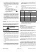


Table Of Contents
- Title Page
- Revision History
- Reader Comments
- Preface
- Table Of Contents
- 1 - Safety
- 2 - Product Records and Maintenance
- 3 - Kubota Diesel Engine
- Kubota 05 E2B Series Workshop Manual (S/N below 280000000)
- Kubota 05-E3B Series Workshop Manual (S/N 280000001 and up)
- Kubota 05-E4B Series Workshop Manual
- 4 - Hydraulic System
- Specifications
- General Information
- Hydraulic Schematics
- Hydraulic Flow Diagrams
- Special Tools
- Troubleshooting
- Testing
- Traction System Operation Testing
- Charge Relief Valve Pressure Test (Using Pressure Gauge)
- Transmission Piston Pump Flow Test (Using Tester with Pressure Gauges and Flow Meter)
- Traction Relief Valve Pressure Test (Using Tester with Pressure Gauges and Flow Meter)
- Wheel Motor Efficiency Test (Using Tester with Pressure Gauges and Flow Meter)
- PTO Pressure Valve Test (Using Pressure Gauge)
- Implement Relief Pressure Test (Using Pressure Gauge)
- Gear Pump Flow Test (Using Tester with Pressure Gauges and Flow Meter)
- Lift Cylinder Internal Leakage Test
- Service and Repairs
- General Precautions for Removing and Installing Hydraulic System Components
- Flush Hydraulic System
- Charge Hydraulic System
- Hydraulic Tank
- Wheel Motors
- Wheel Motor Service
- Transmission
- Transmission Service
- Gear Pump
- Gear Pump Service
- Manual Lift Control Valve (SN Below 313000000)
- Manual Lift Control Valve Service (SN Below 313000000)
- Lift Control Manifold (SN Above 313000000)
- Lift Control Manifold Service (SN Above 313000000)
- Polar TracTM Hydraulic Control Valve
- Polar TracTM Hydraulic Control Valve Service
- Lift Cylinder
- Lift Cylinder Service
- Polar TracTM Lift Cylinder
- Polar TracTM Lift Cylinder Service
- Oil Cooler
- Parker Torqmotor Service Procedure
- 5 - Electrical System
- Electrical Schematics and Diagrams
- Special Tools
- Troubleshooting
- Electrical System Quick Checks
- Component Testing
- Ignition Switch
- Indicator Lights
- Hour Meter
- PTO Switch
- Neutral Switches
- Seat Switch
- Parking Brake Switch (SN Below 310000000)
- Parking Brake Switch (SN Above 310000000)
- Standard Control Module
- Standard Control Module Logic Chart
- PTO Solenoid Valve Coil
- Lift Control Manifold Solenoid Valve Coils (SN Above 313000000)
- Fusible Link Harness
- Diode Assembly
- Glow Relay
- High Temperature Warning Switch
- High Temperature Shutdown Switch
- Dual Temperature Switch (Polar TracTM Machines)
- Deck Lift/Lower Switch (SN Above 313000000)
- Fuel Pump
- Fuel Stop Solenoid
- Glow Controller
- Service and Repairs
- 6 - Chassis
- 7 - Cutting Deck
- 8 - Foldout Diagrams
- Electrical Drawing Designations
- Hydraulic Schematics
- Hydraulic Schematic (SN Below 313000000)
- Hydraulic Schematic (SN Below 313000000) with Rear Attach Lift Kit
- Hydraulic Schematic (SN Below 313000000) with Polar Trac Installed)
- Hydraulic Schematic (SN Below 313000000) with Polar Trac and Rear Attach Lift Kit
- Hydraulic Schematic (SN From 313000001 to 314999999)
- Hydraulic Schematic (SN Above 315000000)
- Electrical Schematics
- Circuit Diagrams
- Wire Harness

Groundsmaster 7200/7210 Page 5 - 33 Electrical System
Battery Service
The battery is t he heart of the e lectrical system. With
regular and proper service, battery life can be extended.
Additionally, battery and electrical component failure
canbeprevented.
CAUTION
When working with batteries, use extreme cau-
tion to avoid splashing or spilling electrolyte.
Electrolyte can destroy clothing and burn skin or
eyes. Always wear safety goggles and a face
shield w hen working with batteries.
Electrolyte Specific Gravity
Fully charged: 1.265 corrected to 80
o
F(26.7
o
C)
Discharged: less than 1.240
Battery Specifications
BCI Group Size 26:
540 CCA at 0
o
F(-17.8
o
C)
Reserve Capacity of 80 minutes at 80
o
F(26.7
o
C)
Dimensions (including terminal posts and caps)
Length 8.2 inches (20.8 cm)
Width 6.8 inches (17.3 cm)
Height 8.0 inches (20.3 cm)
Removal (Fig. 46)
IMPORTANT: Be careful to not damage terminal
posts or cable connectors when removing the bat-
tery cables.
1. Unlatch, raise and support hood. Loosen battery re-
tainer securing the side of the battery to the frame.
2. Loosen nut on ground cable (- ) first and remove
ground cable from battery. This should prevent short cir-
cuiting t he battery, other components or the operators
hands.
3. Once negative cable has been disconnected from
battery, loosen nut on positive cable (+) and remove
positive cable from battery.
4. Make sure battery vent caps are on tightly.
5. Remove battery from the battery compartment to a
serviceareatoallowbetteraccessforservice.
Inspection, Maintenance and Testing
1. Perform the following inspections and maintenance:
A. Check for cracks. Replace battery if cracked or
leaking.
B. Check battery terminal posts for corrosion. Use
wire brush to clean corrosion from posts.
IMPORTANT: Before cleaning t he battery, tape or
block vent holes to the filler caps and make sure the
caps are on tightly.
C. Check for signs of wetness or leakage on the top
of the battery which might indicate a loose or missing
filler cap, overcharging, loose terminal post or over-
filling. Also, check battery case for dirt and oil. Clean
the battery with a solution of baking soda and water,
then rinse it with clean water.
D. Check that the cover seal is not broken away. Re-
place the battery if the seal is broken or leaking.
E. Check the electrolyte level in each cell. If the level
is below the tops of the plates in any cell, fill all cells
with distilled water between the minimum and maxi-
mum fill lines. Charge at 15 to 25 amps for 15 min-
utes to allow sufficient mixing of the electrolyte.
2. Conduct a hydrometer test of the battery electrolyte.
IMPORTANT: Make sure the area around the cells is
clean before opening the battery caps.
A. Measure the specific gravity of each cell with a
hydrometer. Draw electrolyte in and out of the
hydrometer barrel prior to taking a reading to warm-
up the hydrometer. At the same time, take the tem-
perature of the cell.
1. Negative cable
2. Battery
3. Battery tray
4. Flange nut
5. Flat washer
6. Battery retainer
7. Carriage screw
8. Positive cable
Figure 46
5
4
3
2
1
6
7
8
Electrical
System