
Operator's Manual


g004653
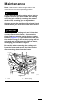
Figure21
1.Cuttingedge3.Wear/slotforming
2.Sailarea4.Crack
CheckingforBentBlades
1.DisengagethePTO,releasethetractionpedal,
andengagetheparkingbrake.
2.MovethethrottlelevertotheSLOWposition,
shutofftheengine,removethekey,andwait
forallmovingpartstostopbeforeleavingthe
operatingposition.
3.Rotatethebladesuntiltheendsfaceforward
andbackward(Figure22).Measurefromalevel
surfacetothecuttingedge,positionA,ofthe
blades(Figure22).Notethisdimension.
g004633
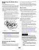
Figure22
1.Measureherefromblade
tohardsurface
2.PositionA
4.Rotatetheoppositeendsofthebladesforward.
5.Measurefromalevelsurfacetothecuttingedge
ofthebladesatthesamepositionasinstep3
above.Thedifferencebetweenthedimensions
obtainedinsteps3and4mustnotexceed
3mm(1/8inch).Ifthisdimensionexceeds
3mm(1/8inch),thebladeisbentandmustbe
replaced;refertoRemovingtheBlades(page
18)andInstallingtheBlades(page19).
WARNING
Abladethatisbentordamagedcould
breakapartandcouldseriouslyinjureor
killyouorbystanders.
•Alwaysreplacebentordamaged
bladewithanewblade.
•Neverleorcreatesharpnotchesin
theedgesorsurfacesofblade.
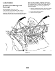
RemovingtheBlades
Bladesmustbereplacedifasolidobjectishit,ifthe
bladeisoutofbalanceorisbent.Toensureoptimum
performanceandcontinuedsafetyconformanceof
themachine,usegenuineTororeplacementblades.
Replacementbladesmadebyothermanufacturers
mayresultinnon-conformancewithsafetystandards.
WARNING
Contactwithasharpbladecancauseserious
injury.
Wearglovesorwrapsharpedgesoftheblade
witharag.
18