
Service Manual


1.
5.
Deck Clutch Service
Failure to get clutch engagement would likely be caused
by a clutch air gap that is too large (see Clutch Adjust-
ment), a circuit fault in clutch electromagnet, or other
electrical problem (see Troubleshooting section of
Chapter 5 - Electrical System).
NOTE: It is recommended that clutch be serviced in
sub-assembl
ies, however, some individual parts of
clutch can be replaced.
1. Follow steps 1 - 7 under Blade Spindle Service to
remo
ve clutch.
2. Remove three (3) locknuts (Item 9) and springs
(Item 10).
3. Separate clutch into two halves; field rotor assembly
(Items 1 - 4) and armature and pulley assembly (Items
5 - 8).
4. To replace pulley bearing (Item 7):
A. Remove retaining ring (Item 8).
B. Put armature and pulley assembly, pulley side
d
own, in an arbor press. Press on bearing collar
(Item 6) to remove bearing and collar. If bearing is
removed, it MUST be replaced.
C. Press collar out of bearing.
D. Make sure both inside and outside race of new
bearing is on a flat surface and press collar into
bearing.
E. Put armature and pulley assembly in arbor press,
p
ulley side up. Put spacers in three (3) locations
between pulley and armature plate to prevent dam-
age to springs. Three (3) stacks of flat washers can
be used for spacers. Make sure extended part of
collar is facing down and press on outer bearing race
to install bearing and collar.
F. Install retaining ring.
5. Assemble clutch halves, install on spindle shaft and
adjust
air gap (see Clutch Adjustment and Clutch Re-
placement).
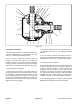
Figure 36
1. Field rotor ass’y 6. Bearing collar
(Items 1 - 4) 7. Pulley bearing
2. Field bearing 8. Retaining r
ing
3. Retaining ring 9. Lock
nut
4. Field coil ass’y 10.
Spring
5. Armature & pulley ass’y 11. Brake plate
(Items 5
- 8)
Cutting Unit
Groundsmaster
®
455-D Page 8 - 25 Repairs