
Operator's Manual


!
7,& )*'3 &5&1 (Fig.11) - Located on right side of
console, lever selects front drive mode. Pull out lockout
knob, move lever rearward for mowing operation and
forward for transport operation, then release knob to
lock selection. Lever must be in LO position to mow.
Middle position (N) is for towing.
Lever must be in LO position to operate
in 4-wheel drive.
Machine must be on a flat surface and
brakes engaged when shifting axle from HI to LO
position.
*(41&
1"+& &%",2
"1+*.( 1"+& "3$)
3&&1*.( )&&, ,3 &5&1
1"+& &%",2 (Fig. 12) - Two foot pedals at the lower
left operate individual wheel brakes for turning
assistance, braking, parking and to aid in obtaining
better sidehill traction. Locking pin is for parking.
"1+*.( 1"+& "3$) (Fig. 12) - A knob on the left side
of console actuates parking brake lock. To engage
parking brake, connect pedals with locking pin, push
down on both pedals and pull parking brake latch out.
To release parking brake, depress both pedals until
parking brake latch retracts.
3&&1*.( )&&, *,3 &5&1 (Fig. 12) - Lever on left side
of console allows steering wheel to be adjusted for
operator comfort.
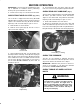
1".20/13 "3$)&2 (Fig. 13) - Four latches secure
cutting unit and wings in upright position for transport
operation.
*(41&
1".20/13 "3$)
/41 &3&1 (Under Hood) - Shows total hours that
machine has been operated.
/1. - In center of steering wheel. Operates only
when key switch is in ON.
Sit on the seat, keep foot off traction pedal. Assure
parking brake is engaged, traction pedal is in
NEUTRAL and cutting unit engagement switch is in the
DISENGAGED position.
Turn ignition switch to ON position. When glow
plug indicator light goes off, engine is ready to START.
Turn ignition key to START. Release key when
engine starts.
To stop, disengage and move all controls to
NEUTRAL and set parking brake. Turn key to OFF and
remove it from switch. Raise and latch all cutting units
in transport position.
! *(
)& '4&, 2823&- -"8 .&&% 3/ #&
01*-&% 6)&. " .&6 &.(*.& *2 23"13&% '/1 3)& '*123
3*-& *' *3 14.2 /43 /' '4&, /1 *' -"*.3&.".$& *2
0&1'/1-&% /. 3)& '4&, 2823&-
Unlatch and raise hood.
Insert a 3/16" hose over bleed screw and run other
end into a container to catch fuel.
Loosen fuel filter / water separator bleed screw
(Fig. 14) a few turns. Pump priming plunger until a
steady stream of fuel comes out of hole in bleed screw.
When fuel stops foaming, tighten the bleed screw
during the downstroke of the priming plunger. Wipe up
any spilled fuel.