
Operator's Manual
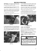


100&+$ +&0 +$$"*"+0 3&0 % (Fig. 9) - Used to
start and stop cutting unit operation. Lift switch and
move forward to actuate cutting unit. Center deck will
engage first followed by wing decks engaging
approximately one second later.
&$1."
100&+$ +&0 +$$"*"+0
3&0 %
),3 )1$ +!& 0,.
%.$" +!& 0,.
"5 3&0 %
%.,00)" ,+0.,)
100&+$ +&0 �
,+0.,)/
,,)+0 "*-".01."
1$"
1") 1$"
,3 0". +!& 0,.
+$&+" &) ."//1."
.+&+$ &$%0
+$&+" ,,)+0 "*-".01."
.+&+$ &$%0
0". &+ 1") .+&+$ &$%0
),3 )1$ +!& 0,. (Fig.9) - Automatically actuates
proper glow period when ignition key is turned to ON
position. Illuminates when glow plugs are actuated.
When glow plugs are heated sufficiently, light goes off
indicating engine is ready to start.
%.$" +!& 0,. (Fig.9) - Illuminates when system
charging circuit malfunctions.
"5 3&0 % (Fig. 9) - Three positions: OFF, ON and
START. Rotate key to START and release key when
engine begins running. To stop engine, rotate key to
OFF.
%.,00)" ,+0.,) (Fig. 9) - Move control forward to
increase engine speed, backward to decrease speed.
100&+$ +&0 � ,+0.,)/ (Fig. 9) - The two outside
levers raise and lower the wing cutting units. The
center lever raises and lowers the whole cutting unit.
Engine must be running to lower cutting unit. When
wing cutting units are raised higher than15_, blades
automatically disengage. To lower cutting unit just
touch levers momentarily.
,,)+0 "*-".01." 1$" (Fig. 9) - Shows
temperature of engine coolant.
1") 1$" (Fig. 9) - Shows amount of fuel in tank.
,3 0". +!& 0,. (Fig. 9) - Indicates low water
level in cooling system.
+$&+" &) ."//1." .+&+$ &$%0 (Fig. 9) -
Indicates dangerously low engine oil pressure.
+$&+" ,,)+0 "*-".01." .+&+$ &$%0 (Fig. 9)
-The red light illuminates and the engine stops when
temperature of coolant exceeds 230_F.
0". &+ 1") +!& 0,. (Fig. 9) - Indicates when there
is water in fuel.
"0 (Fig. 10) - Seat adjusting lever on left side of seat
allows 4 inch fore and aft adjustment. Seat adjusting
knob on front of seat, adjusts seat for operators weight.
&$1."
"0 !'1/0&+$ "2"."0 !'1/0&+$ +,
. 0&,+ "!) (Fig. 11) - Controls forward and
reverse operation. Depress top of pedal to move
forward and bottom to move backward. Ground speed
depends on how far pedal is depressed. For no load,
maximum ground speed, fully depress pedal while
throttle is in FAST. For maximum power under load or
when going uphill, keep engine rpm high by having
throttle in FAST and traction pedal partially engaged. If
engine rpm begins to decrease due to load, gradually
reduce traction pedal pressure until engine speed is
increased.
&$1."
. 0&,+ "!)
-""! ")" 0,.
4)" %� "2".
, (,10 +,
To stop, reduce foot pressure on traction pedal and
allow it to return to center position. On extreme
downhill slopes, apply pressure to REVERSE side of
pedal, or operate with heel on REVERSE and toe on
FORWARD portion of pedal.
-""! ")" 0,. (Fig.11) Ć Cam lever at side of traction
pedal can be rotated to maintain desired speed.
Rotating lever forward decreases speed and backward
increases speed.