
Service Manual


Groundsmaster 4000--D/4010--D Hydraulic SystemPage 4 -- 23
Steering Circuit
A four section gear pump is coupled to the piston (trac-
tion) pump. The third gear pump section supplies hy-
draulic flow to both the steering and lift/lower circuits.
Hydraulic flow from this pump section is delivered to the
two circuits through a proportional flow divider that is lo-
cated in the fan drive manifold. This flow divider splits
pump flow approximately 50% for the steering circuit
and 50% for the lift/lower circuit.
Steering circuit pressure is limited to 1350 PSI (93 bar)
byareliefvalve located in the steeringcontrolvalve. Cir-
cuit pressure can be measured at a test port in the hy-
draulic supply tube.
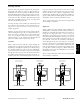
With the steering wheel in the neutral position and the
engine running, flow enters the steering control valve at
the P port and goes through the steering control spool
valve, by--passing the rotary meter (V1) and steering
cylinder. Flow leaves the control valve through the PB
port to the oil filter and traction charge circuit.
Left Turn
When a left turn is made with the engine running, the
turning of the steering wheel positionsthe spool valve so
thatflow goesthroughthe topof thespool.Flowentering
the steering control valve at the P port goes through the
spool and is routed to two places. First, most of the flow
throughthevalveisby--passedoutthePBportbackto
the oil filter and traction charge circuit. Second, the re-
mainder of the flow is drawn through the rotary meter
(V1) and out the L port. Pressure retracts the steering
cylinder piston for a left turn. The rotary meter ensures
that the oil flow to the cylinder is proportional to the
amount of the turning on the steering wheel. Fluid leav-
ing the cylinder flows back through the spool valve then
through the T port and to the hydraulic reservoir.
The steering control valve returns to the neutral position
when turning is completed.
Right Turn
When a right turn is made with the engine running, the
turningof thesteering wheelpositionsthe spoolvalve so
that flow goes through the bottom of the spool. Flow en-
tering the steering control valve at the P port goes
through the spool and is routed to two places. As in a left
turn, most of the flow through the valve is by--passed out
the PB port back to the oil f ilter and traction charge cir-
cuit. Also like a left turn, the remainder of the flow is
drawn through rotary meter (V1) but goes out port R.
Pressure extends the steering cylinder piston for a right
turn. The rotarymeter ensures that the oil flow to the cyl-
inder is proportional to the amount of the turning on the
steering wheel. Fluid leaving the cylinder flows back
through the spool valve then through the T port and to
the hydraulic reservoir.
The steering control valve returns to the neutral position
when turning is completed.
Figure 14
1350
PSI
PB
STEERING
T
R
P
L
PISTON MOVEMENT
CONTROL
1350
PSI
PB
STEERING CYLINDER
STEERING
T
R
P
L
PISTON MOVEMENT
CONTROL
1350
PSI
PB
STEERING CYLINDER
STEERING
T
R
P
L
CONTROL
LEFT TURN
NEUTRAL POSITION
RIGHT TUR N
NO PISTON MOVEMENT
STEERING CYLINDER
Hydraulic
System