
Operator's Manual


41
Note: Make sure you have not reached the end of the
neutral lock slot (Fig. 57). If you have, shorten the control
rod. Refer to Adjusting the Control Rod on page 41.
6. If the wheel turns while holding the drive lever in
neutral position, the neutral stud needs to be adjusted
(Fig. 50). If the wheel does not rotate, then go to
step 12.
7. Loosen the nut against the yoke (Fig. 55).
8. Adjust the adjustment stud until the respective drive
wheel stops while holding the drive in neutral position
(increase resistance) (Fig. 50).
9. Turn the adjusting bolt approximately 1/4 turn
clockwise if the wheel is turning in reverse and turn
the bolt approximately 1/4 turn counter–clockwise if
the wheel is turning forward (Fig. 50).
10. Release the drive lever to the forward drive position
and squeeze back into the neutral position (Fig. 57).
Check to see if the wheel stops. If not, repeat steps 8
and 9.
11. After adjustments are made, tighten the nut against the
yoke.
12. Repeat this procedure for the opposite side.
Adjusting the Control Rods
Checking the Control Rods
1. With rear of machine still on jack stands and engine
running at full throttle, move the speed control lever to
the medium speed position.
Note: The OPC levers must be held down whenever the
speed control lever is out of the neutral position or the
engine will kill.
2. Move the respective drive lever upward until it reaches
the neutral position and engage neutral locks.
3. If the tire rotates in either direction, the length of the
control rod will need to be adjusted.
Adjusting the Control Rods
1. Adjust the rod length by releasing the drive lever and
removing the hairpin cotter pin and clevis pin
(Fig. 56). Rotate the rod in the rod fitting (Fig. 57).
2. Lengthen the rod if the tire is turning in reverse and
shorten the rod if the tire is turning forward.
3. Rotate the rod several turns if the tire is rotating fast.
Then, adjust the rod in 1/2 turn increments.
4. Place the clevis pin into the drive lever (Fig. 56).
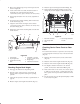
m–6639
6
5
3
7
2
4
1
Figure 56
1. Left handle shown
2. Neutral lock
3. Clevis pin
4. Drive lever
5. Control rod
6. Operator Presence
Control lever (OPC)
7. Hairpin cotter
5. Release and engage neutral lock checking that the tire
does not rotate. Continue this process until the tire
does not rotate.
6. Install hairpin cotter between drive levers and neutral
locks and into clevis pins (Fig. 56).
Note: Make sure the clevis pins are inserted into the
neutral locks.
7. Repeat this adjustment for opposite side.
5
8
4
6
7
1
2
3
m–7557
Figure 57
1. Handle
2. Neutral lock
3. Neutral position (engaged)
4. Drive lever
5. Full speed forward
6. Control rod
7. Neutral lock slot
8. Grip
Adjusting the Tracking
1. Remove the machine from any jack stands.
2. Check the rear tire pressure. Refer to Checking the
Tire Pressure Service on page 33.