
Service Manual


CHASSIS
4 - 8 Mid-Size Walk Behind Service Manual
Adjusting the Brake
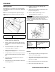
The brake lever is on the upper control bar (Figure 36).
If the parking brake does not hold securely, adjustment
is required.
Note: For the initial adjustment, adjust the wing nut
until it is 1-1/4 inches (32mm) from the top of the rod
(Figure 37).
Figure 36
m-5233
1. Park the machine on a level surface, disengage
the PTO, and set the parking brake.
2. Stop the engine, remove the key, and wait for all
moving parts to stop before leaving the operating
position.
3. Check the brake before you adjust it; refer to
”Checking the Brake" on page 4 - 7.
4. Release the parking brake; refer to ”Releasing the
Parking Brake" on page 4 - 4.
5. To adjust the brake, remove the hair pin cotter and
washer from the brake lever and trunnion (Figure
37).
6. Rotate the wing nut clockwise to increase the
braking pressure.
7. Rotate the wing nut counterclockwise to decrease
the braking pressure.
8. Install the trunnion into hole F (Figure 37).
Tighten the wing nut.
9. Secure trunnion to brake lever with washer and
hair pin cotter (Figure 37).
10. Check the brake operation again; refer to
”Checking the Brake" on page 4 - 7.
With the parking brake released, the rear
wheels must rotate freely when you push the mower. If
brake action and free wheel rotation cannot be
achieved, examine the brake system components for
wear or damage.
Figure 37
m-6512
Brake Band (T-Bar - Gear Drive)
Removal
1. Turn the engine off and remove the high tension
wire(s) from the spark plug(s).
2. Jack up the machine until the tire is off the floor.
Support the machine with jack stands or blocks to
prevent it from falling.
3. Remove rear wheel and tire from the wheel hub.
4. Remove the wheel hub from the axle.
(1) Upper control bar (2) Parking brake lever (set
position)
(1) Hair pin cotter and
washer
(2) Trunnion
(3) Brake lever
(4) Wing nut
(5) Hole F
(6) Initial adjustment - 1-1/4
inch (32 mm)
(7) Rod
Important