
Service Manual


Mid-Size Walk Behind Service Manual 5 - 9
HYDRAULIC DRIVE SYSTEMS
6. Connect rod to upper control bars with previously
removed hairpin cotter (Figure 80).
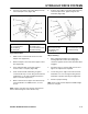
Figure 81
m-5263
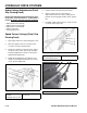
Right Control Rod
1. Slide rod into control bracket and secure with
hairpin cotter (Figure 82).
2. Remove hairpin cotter and rod from upper control
bars (Figure 80).
3. Press and hold upper control bars against
reference bar, so stop hits (Figure 80).
4. Push rod full forward until bearing is against
control bracket stop. Loosen wing nut and thread
turnbuckle in or out until rod aligns with holes in
upper control bars (Figure 82).
5. When rod and holes in upper control bars line up,
rotate turnbuckle one additional turn, so rod is
shorter.
Note: Upper control bar stop must hit reference bar
before roller bearing hits control bracket stop.
6. Connect rod to upper control bars with previously
removed hairpin cotter, tighten wing nut and
turnbuckle (Figure 80).
Figure 82
m-5262
Adjust Tracking
1. After completing assembly, check machine
tracking. Operate machine by holding upper
control bar against reference bar with wheel drive
engaged.
2. If machine does not track straight, moves more
right or left, adjustment is required.
3. Loosen wing nut on right control rod and rotate
turnbuckle in or out to change tracking. Secure
turnbuckle in position with wing nut (Figure 82).
4. Check for proper tracking.
Note: Control rods must be adjusted if handle height
position is changed.
(1) Control rod-left
(2) Control bracket
(3) Rod fitting
(4) Clevis pin
(5) Washer
(6) Hairpin cotter
(7) Control bracket stop
(8) Roller bearing
(1) Control rod-right
(2) Control bracket
(3) Hairpin cotter
(4) Wing nut
(5) Turnbuckle
(6) Control bracket stop
(7) Roller bearing