
Operator's Manual


31
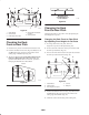
2. Check adjustment by inserting feeler gauge thru slots
next to studs (Fig. 36).
3. The proper disengaged clearance between the clutch
plates is 0.012–0.018 inch (0.30-0.45 mm). It will be
necessary to check this clearance at each of the three
slots to ensure the plates are parallel to each other.
m–2600
1
2
3
Figure 36
1. Adjusting nut
2. Slot
3. Feeler gauge
Servicing the Brakes
Service Interval/Specification
Before each use, check brakes on both a level surface and
slope.
Always set the parking brake when you stop the machine or
leave it unattended. If the parking brake does not hold
securely, an adjustment is required.
Checking the Brake
1. Park the machine on a level surface, disengage the PTO.
2. Stop the engine, remove the key, and wait for all
moving parts to stop before leaving the operating
position.
3. Push the neutral/brake lock forward to set the brake.
4. Rear wheels must lock when you try to push the
machine forward or backward. Adjustment is required if
the wheels turn and do not lock. Refer to Adjusting the
Brake on page 31.
5. Release the brake and move neutral/brake lock to the
neutral position. Move the machine lightly,
approximately 1/2 in. (13 mm). Wheels should rotate
freely.
6. If both conditions are met, no adjustment is required.
Adjusting the Brakes
The brake lever is on the upper control bar (Fig. 12). If the
parking brake does not hold securely, an adjustment is
required.
Note: For the initial adjustment, adjust the wing nut until it
is 1–1/4 inches from the top of the rod (Fig. 37).
1. Park the machine on a level surface, disengage the PTO,
and set the parking brake.
2. Stop the engine, remove the key, and wait for all
moving parts to stop before leaving the operating
position.
3. Check the brake before you adjust it; refer to Checking
the Brakes, page 31.
4. Release the parking brake; refer to Releasing the
Parking Brake, page 19.
5. To adjust the brake remove the hair pin cotter and
washer from the bell crank and trunnion (Fig. 37).
6. Rotate the wing nut clockwise to increase the braking
pressure.
7. Rotate the wing nut counterclockwise to decrease the
braking pressure.
8. Install the trunnion into the hole for the brake rod
(Fig. 37). Tighten the wing nut.
9. Secure trunnion to brake lever with washer and hair pin
cotter (Fig. 37).
10. Check the brake operation again; refer to Checking the
Brake, page 31.