
Service Manual


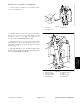


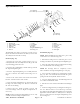
Table Of Contents
- Title Page
- Revision History
- Reader Comments
- Preface
- Table of Contents
- 1 - Safety
- 2 - Product Records and Maintenance
- 3 - Kubota Diesel Engine
- Kubota Diesel Engine Service Manual
- 4 - Hydraulic System
- Specifications
- General Information
- Hydraulic Schematic
- Hydraulic Flow Diagrams
- Special Tools
- Troubleshooting
- Testing
- Traction Circuit Charge Pressure (Using Pressure Gauge)
- Traction Circuit Relief Pressure (Using Pressure Gauge)
- Counterbalance Pressure (Using Pressure Gauge)
- Rear Traction Circuit (RV) Relief Pressure (Using Pressure Gauge)
- Traction Circuit Reducing Valve (PR) Pressure (Using Pressure Gauge)
- Cutting Deck Circuit Pressure (Using Pressure Gauge)
- PTO Relief Pressure (Using Tester with Pressure Gauges and Flow Meter)
- Cutting Deck Motor Case Drain Leakage (Using Tester with Pressure Gauges and Flow
- Cutting Deck Gear Pump Flow
- Steering Circuit Relief Pressure
- Lift/Lower Circuit Relief Pressure
- Steering and Lift/Lower Gear Pump Flow
- Engine Cooling Fan Circuit
- Engine Cooling Fan Circuit Gear Pump Flow
- Adjustments
- Service and Repairs
- General Precautions for Removing and Installing Hydraulic System Components
- Check Hydraulic Lines and Hoses
- Flush Hydraulic System
- Charge Hydraulic System
- Hydraulic Reservoir
- Hydraulic Oil Cooler
- Gear Pump
- Gear Pump Service
- Traction Circuit
- Piston (Traction) Pump
- Piston (Traction) Pump Service
- Rear Axle Motor
- Front Wheel Motor
- Rear Axle and Front Wheel Motor Service
- 4WD Manifold
- 4WD Manifold Service
- Traction (Flow Divider) Manifold
- Traction (Flow Divider) Manifold Service
- Filter Manifold
- Filter Manifold Service
- Steering and Cooling Fan Circuits
- Steering Valve
- Steering Valve Service
- Steering Cylinder
- Steering Cylinder Service
- Engine Cooling Fan Motor
- Engine Cooling Fan Motor Service
- Fan Drive Manifold
- Fan Drive Manifold Service
- PTO Circuit
- Cutting Deck Motor
- Cutting Deck Motor Service
- PTO Manifold
- PTO Manifold Service
- Lift/Lower Circuit
- Lift/Lower Control Valve
- Lift/Lower Control Valve Service
- Side Deck Lift Cylinder
- Front Deck Lift Cylinder
- Lift Cylinder Service
- Counterbalance Manifold
- Counterbalance Manifold Service
- Eaton Piston Pump Repair Information
- Eaton Piston Motor Repair Information
- 5 - Electrical System
- General Information
- Special Tools
- Troubleshooting
- Electrical System Quick Checks
- Component Testing
- Ignition Switch
- Fuses
- Warning Lights
- PTO Switch
- Alarm Silence and Temperature Override Switches
- Transport / 4WD Switch
- Flow Divider Switch
- Cooling Fan Switch
- Seat Switch
- Parking Brake Switch
- Hour Meter
- Audio Alarm
- Glow and Power Relays
- Start, Engine Shutdown, Seat, PTO, PTO Overtemp, Alarm and Over Temperature Relays
- Hydraulic Valve Solenoids
- TEC-5002 Controller
- Fuel Sender
- Fuel Gauge
- Fuel Pump
- Glow Controller
- Temperature Sender
- Dual Temperature Switch
- Temperature Gauge
- Traction Neutral Switch
- Diode Assemblies
- Diode Circuit Board
- Fusible Link Harness
- Cutting Deck Position Switch
- Engine Coolant and Hydraulic Oil Temperature Senders
- Service and Repairs
- 6 - Axles, Planetaries and Brakes
- 7 - Chassis
- 8 - Cutting Decks
- 9 - Foldout Drawings
- Hydraulic Schematic
- Electrical Schematic
- Glow Plug Circuits
- Crank Circuits
- Run (Transport) Circuits
- Run (Mow) Circuits
- High Temperature Warning Cuircuits
- Over Temperature Shutdown Circuits
- Engine Wire Harness
- Engine Wire Harness Diagram
- Front Wire Harness
- Front Wire Harness Diagram
- Console Wire Harness
- Console Wire Harness DIagram

Groundsmaster 4000--D Page 6 -- 19 Axles, Planetaries and Brakes
Bevel Gear Case and Axle Case Installation
1. Coat new shaft seal with grease and install in axle
case as shown (Fig. 20).
1. Axle case
2. Bevel gear case
3. Shaft seal
Figure 20
1
2
3
2. Install the lower bevel gear and bevel gear shaft in
the axle case cover. Coat a new O-ring with grease and
install the axle case cover (Fig. 21). Tighten cover
screws from 17 to 20 ft -lb (23 to 27 N--m).
3. Slide the bevel gear case over the bevel gear shaft
andinstallthebevelgearandcollar.Makesurethebevel
gear shaft is completely seated in the upper and lower
bearings (Fig. 21).
4. Install the knuckle pin. Use medium strength Loctite
thread locker and tighten the knuckle pin mounting bolts
from 17 to 20 ft-lb (23 to 27 N--m).
1. Axle case cover
2. Lower bevel gear
3. Bevel gear shaft
4. Lower bearing
5. Upper bevel gear
6. Collar
7. Upper bearing
8. Knuckle pin
Figure 21
1
2
3
4
5
6
7
8
Axles, Planetaries
and Brakes