
Service Manual

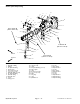


Table Of Contents
- Title Page
- Revision History
- Reader Comments
- Preface
- Table of Contents
- 1 - Safety
- 2 - Product Records and Maintenance
- 3 - Kubota Diesel Engine
- Kubota Diesel Engine Service Manual
- 4 - Hydraulic System
- Specifications
- General Information
- Hydraulic Schematic
- Hydraulic Flow Diagrams
- Special Tools
- Troubleshooting
- Testing
- Traction Circuit Charge Pressure (Using Pressure Gauge)
- Traction Circuit Relief Pressure (Using Pressure Gauge)
- Counterbalance Pressure (Using Pressure Gauge)
- Rear Traction Circuit (RV) Relief Pressure (Using Pressure Gauge)
- Traction Circuit Reducing Valve (PR) Pressure (Using Pressure Gauge)
- Cutting Deck Circuit Pressure (Using Pressure Gauge)
- PTO Relief Pressure (Using Tester with Pressure Gauges and Flow Meter)
- Cutting Deck Motor Case Drain Leakage (Using Tester with Pressure Gauges and Flow
- Cutting Deck Gear Pump Flow
- Steering Circuit Relief Pressure
- Lift/Lower Circuit Relief Pressure
- Steering and Lift/Lower Gear Pump Flow
- Engine Cooling Fan Circuit
- Engine Cooling Fan Circuit Gear Pump Flow
- Adjustments
- Service and Repairs
- General Precautions for Removing and Installing Hydraulic System Components
- Check Hydraulic Lines and Hoses
- Flush Hydraulic System
- Charge Hydraulic System
- Hydraulic Reservoir
- Hydraulic Oil Cooler
- Gear Pump
- Gear Pump Service
- Traction Circuit
- Piston (Traction) Pump
- Piston (Traction) Pump Service
- Rear Axle Motor
- Front Wheel Motor
- Rear Axle and Front Wheel Motor Service
- 4WD Manifold
- 4WD Manifold Service
- Traction (Flow Divider) Manifold
- Traction (Flow Divider) Manifold Service
- Filter Manifold
- Filter Manifold Service
- Steering and Cooling Fan Circuits
- Steering Valve
- Steering Valve Service
- Steering Cylinder
- Steering Cylinder Service
- Engine Cooling Fan Motor
- Engine Cooling Fan Motor Service
- Fan Drive Manifold
- Fan Drive Manifold Service
- PTO Circuit
- Cutting Deck Motor
- Cutting Deck Motor Service
- PTO Manifold
- PTO Manifold Service
- Lift/Lower Circuit
- Lift/Lower Control Valve
- Lift/Lower Control Valve Service
- Side Deck Lift Cylinder
- Front Deck Lift Cylinder
- Lift Cylinder Service
- Counterbalance Manifold
- Counterbalance Manifold Service
- Eaton Piston Pump Repair Information
- Eaton Piston Motor Repair Information
- 5 - Electrical System
- General Information
- Special Tools
- Troubleshooting
- Electrical System Quick Checks
- Component Testing
- Ignition Switch
- Fuses
- Warning Lights
- PTO Switch
- Alarm Silence and Temperature Override Switches
- Transport / 4WD Switch
- Flow Divider Switch
- Cooling Fan Switch
- Seat Switch
- Parking Brake Switch
- Hour Meter
- Audio Alarm
- Glow and Power Relays
- Start, Engine Shutdown, Seat, PTO, PTO Overtemp, Alarm and Over Temperature Relays
- Hydraulic Valve Solenoids
- TEC-5002 Controller
- Fuel Sender
- Fuel Gauge
- Fuel Pump
- Glow Controller
- Temperature Sender
- Dual Temperature Switch
- Temperature Gauge
- Traction Neutral Switch
- Diode Assemblies
- Diode Circuit Board
- Fusible Link Harness
- Cutting Deck Position Switch
- Engine Coolant and Hydraulic Oil Temperature Senders
- Service and Repairs
- 6 - Axles, Planetaries and Brakes
- 7 - Chassis
- 8 - Cutting Decks
- 9 - Foldout Drawings
- Hydraulic Schematic
- Electrical Schematic
- Glow Plug Circuits
- Crank Circuits
- Run (Transport) Circuits
- Run (Mow) Circuits
- High Temperature Warning Cuircuits
- Over Temperature Shutdown Circuits
- Engine Wire Harness
- Engine Wire Harness Diagram
- Front Wire Harness
- Front Wire Harness Diagram
- Console Wire Harness
- Console Wire Harness DIagram

Groundsmaster 4000--D Hydraulic SystemPage 4 -- 81
Removal (Fig. 57)
1. Park machine on a level surface, lower cutting
decks, stop engine, apply parking brake and remove
key from the ignition switch.
2. Read the General Precautions for Removing and
Installing Hydraulic System Components at the begin-
ning of the Service and Repairs section of this chapter.
NOTE: To ease installation, tag the hydraulic hoses to
show their correct position on the wheel motor.
3. Disconnect hydraulic hoses and tubes from wheel
motor. Put caps or plugs on motor ports and hose open-
ings to prevent contamination.
IMPORTANT: Before loosening fasteners, support
wheel motor to prevent motor from falling during re-
moval.
4. Remove wheel motor using Figure 57 as a guide.
5. If hydraulic fittings are to be removed from motor,
mark fitting orientation to allow correct assembly. Re-
move fittings from motor and discard O--rings.
Installation (Fig. 57)
1. If fittings were removed from motor, lubricate and
place new O--rings onto fittings. Install fittings into port
openingsusingmarksmadeduringtheremovalprocess
to properly orientate fittings. Tighten fittings (see Hy-
draulic Fitting Installation in the General Information
section of this chapter).
2. Positionwheelmotortobrakeassemblymakingsure
that arrows on the side of motor case point upward.
3. Align splines on motor shaft and splined brake shaft.
Slide motor into brake assembly.
4. Secure motor to brake assembly with cap screws
andflatwashers. Tighten capscrews from75 to85 ft--lb
(101 to 115 N--m).
5. Remove plugs from wheel motor ports and hose
openings. Attach hydraulic hoses and tubes to wheel
motor (see Hydraulic Hose and Tube Installation in the
General Information section of this chapter).
6. Fill reservoir with hydraulic fluid as required.
Hydraulic
System