
Service Manual


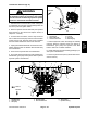

Table Of Contents
- Title Page
- Revision History
- Reader Comments
- Preface
- Table Of Contents
- 1 - Safety
- 2 - Product Records and Maintenance
- 3 - Kubota Diesel Engine
- 4 - Hydraulic System
- Specifications
- General Information
- Hydraulic Schematics
- Hydraulic Flow Diagrams
- Special Tools
- Troubleshooting
- Testing
- Traction System Operation Testing
- Charge Relief Valve Pressure Test (Using Pressure Gauge)
- Transmission Piston Pump Flow Test (Using Tester with Pressure Gauges and Flow Meter)
- Traction Relief Valve Pressure Test (Using Tester with Pressure Gauges and Flow Meter)
- Wheel Motor Efficiency Test (Using Tester with Pressure Gauges and Flow Meter)
- PTO Pressure Valve Test (Using Pressure Gauge)
- Implement Relief Pressure Test (Using Pressure Gauge)
- Gear Pump Flow Test (Using Tester with Pressure Gauges and Flow Meter)
- Lift Cylinder Internal Leakage Test
- Service and Repairs
- General Precautions for Removing and Installing Hydraulic System Components
- Flush Hydraulic System
- Charge Hydraulic System
- Hydraulic Tank
- Wheel Motors
- Wheel Motor Service
- Transmission
- Transmission Service
- Gear Pump
- Gear Pump Service
- Manual Lift Control Valve (SN Below 313000000)
- Manual Lift Control Valve Service (SN Below 313000000)
- Lift Control Manifold (SN Above 313000000)
- Lift Control Manifold Service (SN Above 313000000)
- Polar TracTM Hydraulic Control Valve
- Polar TracTM Hydraulic Control Valve Service
- Lift Cylinder
- Lift Cylinder Service
- Polar TracTM Lift Cylinder
- Polar TracTM Lift Cylinder Service
- Oil Cooler
- 5 - Electrical System
- Electrical Schematics and Diagrams
- Special Tools
- Troubleshooting
- Electrical System Quick Checks
- Component Testing
- Ignition Switch
- Indicator Lights
- Hour Meter
- PTO Switch
- Neutral Switches
- Seat Switch
- Parking Brake Switch (SN Below 310000000)
- Parking Brake Switch (SN Above 310000000)
- Standard Control Module
- Standard Control Module Logic Chart
- PTO Solenoid Valve Coil
- Lift Control Manifold Solenoid Valve Coils (SN Above 313000000)
- Fusible Link Harness
- Diode Assembly
- Glow Relay
- High Temperature Warning Switch
- High Temperature Shutdown Switch
- Dual Temperature Switch (Polar TracTM Machines)
- Deck Lift/Lower Switch (SN Above 313000000)
- Fuel Pump
- Fuel Stop Solenoid
- Glow Controller
- Service and Repairs
- 6 - Chassis
- 7 - Cutting Deck
- 8 - Foldout Diagrams
- Electrical Drawing Designations
- Hydraulic Schematics
- Hydraulic Schematic (SN Below 313000000)
- Hydraulic Schematic (SN Below 313000000) with Rear Attach Lift Kit
- Hydraulic Schematic (SN Below 313000000) with Polar Trac Installed)
- Hydraulic Schematic (SN Below 313000000) with Polar Trac and Rear Attach Lift Kit
- Hydraulic Schematic (SN From 313000001 to 314999999)
- Hydraulic Schematic (SN Above 315000000)
- Electrical Schematics
- Circuit Diagrams
- Wire Harness

Groundsmaster 7200/7210Hydraulic System Page 4 – 54
10.Remove oil filter from transmission. Discard filter. If
necessary, remove gear pump from transmission (see
Gear Pump Removal in this section).
NOTE: Two (2) 8 mm eyebolts can be installed into
threaded bosses in top of transmission to allow use of
a lift or hoist to remove transmission (Fig. 37).
CAUTION
Support transmission assembly when removing
it from the flywheel housing to prevent it from fal-
ling and causing personal injury.
11. Remove seven (7) cap screws and lock washers that
secure the transmission to the flywheel housing. Note
location of the shorter cap screw for assembly pur-
poses.
IMPORTANT: Make sure to not damage the trans-
mission, flywheel housing, hydraulic lines, electri-
cal harness or other parts while removing
transmission.
12.Move transmission assembly toward the front of the
machine and away from the flywheel housing and cou-
pler on engine flywheel. Lift transmission from machine.
13.Locate and note location of two (2) dowel pins from
transmission and flywheel housing.
14.On both sides of transmission, remove retaining ring
that secures pump control rod end onto transmission
control arm (Fig. 36). Slide control rod from control arm.
15.If hydraulic fittings are to be removed from transmis-
sion, mark fitting orientation to allow correct assembly.
Remove hydraulic fittings from transmission as needed.
Discard fitting O–rings.
16.Inspect flywheel housing and coupler on engine fly-
wheel for evidence of wear or damage.
Transmission Installation (Fig. 35)
1. Make sure that flywheel coupler and flywheel hous-
ing are secure on engine (see Engine Installation in the
Service and Repairs section of Chapter 3 – Kubota Die-
sel Engine).
2. If hydraulic fittings were removed from transmission,
lubricate and install new O–rings to fittings. Install fit-
tings into transmission ports (see Hydraulic Fitting
Installation in the General Information section of this
chapter). Tighten fittings to torque values identified in
Figure 38).
3. If gear pump was removed from transmission, install
gear pump (see Gear Pump Installation in this section).
4. Slide both pump control rods onto transmission con-
trol arms and secure with retaining rings (Fig. 36).
Figure 38
20 to 26 ft–lb
(28 to 35 N–m)
35 to 43 ft–lb
(48 to 58 N–m)
35 to 43 ft–lb
(48 to 58 N–m)
58 to 72 ft–lb
(79 to 97 N–m)
58 to 72 ft–lb
(79 to 97 N–m)
60 to 74 ft–lb
(82 to 100 N–m)
81 to 99 ft–lb
(110 to 134 N–m)
60 to 74 ft–lb
(82 to 100 N–m)
9 to 11 ft–lb
(13 to 15 N–m)