
Service Manual


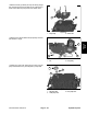


Table Of Contents
- Title Page
- Revision History
- Reader Comments
- Preface
- Table Of Contents
- 1 - Safety
- 2 - Product Records and Maintenance
- 3 - Kubota Diesel Engine
- 4 - Hydraulic System
- Specifications
- General Information
- Hydraulic Schematics
- Hydraulic Flow Diagrams
- Special Tools
- Troubleshooting
- Testing
- Traction System Operation Testing
- Charge Relief Valve Pressure Test (Using Pressure Gauge)
- Transmission Piston Pump Flow Test (Using Tester with Pressure Gauges and Flow Meter)
- Traction Relief Valve Pressure Test (Using Tester with Pressure Gauges and Flow Meter)
- Wheel Motor Efficiency Test (Using Tester with Pressure Gauges and Flow Meter)
- PTO Pressure Valve Test (Using Pressure Gauge)
- Implement Relief Pressure Test (Using Pressure Gauge)
- Gear Pump Flow Test (Using Tester with Pressure Gauges and Flow Meter)
- Lift Cylinder Internal Leakage Test
- Service and Repairs
- General Precautions for Removing and Installing Hydraulic System Components
- Flush Hydraulic System
- Charge Hydraulic System
- Hydraulic Tank
- Wheel Motors
- Wheel Motor Service
- Transmission
- Transmission Service
- Gear Pump
- Gear Pump Service
- Manual Lift Control Valve (SN Below 313000000)
- Manual Lift Control Valve Service (SN Below 313000000)
- Lift Control Manifold (SN Above 313000000)
- Lift Control Manifold Service (SN Above 313000000)
- Polar TracTM Hydraulic Control Valve
- Polar TracTM Hydraulic Control Valve Service
- Lift Cylinder
- Lift Cylinder Service
- Polar TracTM Lift Cylinder
- Polar TracTM Lift Cylinder Service
- Oil Cooler
- 5 - Electrical System
- Electrical Schematics and Diagrams
- Special Tools
- Troubleshooting
- Electrical System Quick Checks
- Component Testing
- Ignition Switch
- Indicator Lights
- Hour Meter
- PTO Switch
- Neutral Switches
- Seat Switch
- Parking Brake Switch (SN Below 310000000)
- Parking Brake Switch (SN Above 310000000)
- Standard Control Module
- Standard Control Module Logic Chart
- PTO Solenoid Valve Coil
- Lift Control Manifold Solenoid Valve Coils (SN Above 313000000)
- Fusible Link Harness
- Diode Assembly
- Glow Relay
- High Temperature Warning Switch
- High Temperature Shutdown Switch
- Dual Temperature Switch (Polar TracTM Machines)
- Deck Lift/Lower Switch (SN Above 313000000)
- Fuel Pump
- Fuel Stop Solenoid
- Glow Controller
- Service and Repairs
- 6 - Chassis
- 7 - Cutting Deck
- 8 - Foldout Diagrams
- Electrical Drawing Designations
- Hydraulic Schematics
- Hydraulic Schematic (SN Below 313000000)
- Hydraulic Schematic (SN Below 313000000) with Rear Attach Lift Kit
- Hydraulic Schematic (SN Below 313000000) with Polar Trac Installed)
- Hydraulic Schematic (SN Below 313000000) with Polar Trac and Rear Attach Lift Kit
- Hydraulic Schematic (SN From 313000001 to 314999999)
- Hydraulic Schematic (SN Above 315000000)
- Electrical Schematics
- Circuit Diagrams
- Wire Harness

Groundsmaster 7200/7210Hydraulic System Page 4 – 58
5. Remove filter bypass plug, spring and valve from
transmission pump body. Remove and discard O–ring
from plug.
1. Filter bypass plug 2. Bypass valve
Figure 41
1
2
6. Remove pressure valve plug, spring and valve from
transmission pump body. Remove and discard O–ring
from plug.
7. Remove charge relief plug, spring and valve from
transmission pump body. Remove and discard O–ring
from plug.
1. Pressure valve plug 2. Charge relief plug
Figure 42
1
2
8. Remove two (2) bolts that secure accumulator cover
to transmission pump body.
9. Remove cover, gasket, collar, spring and piston from
pump body. For assembly purposes, note that hole in
collar is toward the outside of the pump body. Discard
gasket.
1. Accumulator cover
2. Collar
3. Piston
Figure 43
1
2
3
10.Remove two (2) hex plugs from pump body. Remove
and discard O–rings from plugs.
11. Remove four (4) socket head plugs from pump body.
1. Hex plug (2 used) 2. Socket plug (4 used)
Figure 44
1
2