
Service Manual


g230841
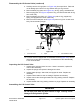
Figure103
1.Liftcontrolvalve4.Counterbalancemanifold7.Lockwasher(2each)
2.Hydraulicadapter
5.Hydraulictting8.Flatwasher(2each)
3.Hydraulictube
6.Bolt(2each)
Note:Earlymachinescamettedwithaliftcontrolvalvethatincorporated
thecounterbalancevalve(Figure102).Onlatermachines(machineserial
numbersbelow311000000)orearlymachinesthathavebeenupdated),the
counterbalancevalveislocatedinaseparatemanifold(Figure103).Checkthe
liftvalvecongurationusedbeforeservicingtheliftvalve.
RemovingtheLiftControlValve
1.Parkthemachineonalevelsurface,engagetheparkingbrake,lowerthe
cuttingdeck(orimplement),andshutofftheengine.Removethekeyfrom
thekeyswitch.
2.ReadtheGeneralPrecautionsforRemovingandInstallingtheHydraulic
SystemComponents(page5–77).
3.Removefueltankfrommachine;refertoRemovingtheFuelTank(page
3–10)orRemovingtheFuelT ank(page4–16).
4.Labelallhydraulicconnectionsforassemblypurposes.Cleanhydraulichose
endspriortodisconnectingthehoses.
CAUTION
Operateallhydrauliccontrolstorelievesystempressureandavoid
injuryfrompressurizedhydraulicuid.
5.Disconnecthoseconnectionsfromhydraulicttingsonliftcontrolvalve.
Allowhosestodrainintoasuitablecontainer.
6.Putcapsorplugsondisconnectedhosesandttingstoprevent
contamination.
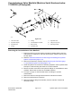
7.Removecotterpin(item14inFigure102)andpinthatsecurelinktubeto
controlvalve.
8.Remove2bolts(item11inFigure102),2lockwashers,and2atwashers
thatsecureliftcontrolvalvetomachine
9.Removecontrolvalvefromthemachine.
10.Removehydraulicttingsasnecessaryfromthecontrolvalve.Discardall
removedO-rings
HydraulicSystem:ServiceandRepairs
Page5–128
Groundsmaster
®
3280-D/3320
05138SLRevB