
Operator's Manual


41
the listed range for all the following material properties and
it meets industry standards. We do not recommend the use
of synthetic fluid. Consult with your lubricant distributor to
identify a satisfactory product Note: Toro will not assume
responsibility for damage caused by improper substitutions,
so use only products from reputable manufacturers who
will stand behind their recommendation.
Material Properties:
Viscosity, ASTM D445 cSt @ 40_C 55 to 62
cSt @ 100_C 9.1 to 9.8
Viscosity Index ASTM D2270 140 – 152
Pour Point, ASTM D97 –35_F to –46_F
Industry Specifications:
API GL–4, AGCO Powerfluid 821 XL, Ford New
Holland FNHA–2–C–201.00, Kubota UDT, John Deere
J20C, Vickers 35VQ25 and Volvo WB–101/BM.
Note: Fluid to operate the power steering is supplied by the
hydraulic system transmission charge pump.
Cold weather start–up may result in “stiff” operation of the
steering until the hydraulic system has warmed up. Using
proper weight hydraulic oil in system will minimize this
condition.
Note: Many hydraulic fluids are almost colorless, making it
difficult to spot leaks. A red dye additive for the hydraulic
system oil is available in 2/3 oz. (20 ml) bottles. One bottle
is sufficient for 4–6 gal (15–22 1) of hydraulic oil. Order
part no. 44–2500 from your authorized Toro distributor.
1. Lower deck to shop floor, set parking brake, and turn
engine OFF. Block the two rear wheels.
2. Jack up both sides of the front axle and support it with
jack stands.
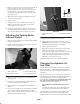
3. Clean the area around the hydraulic oil filter and
remove the filter (Fig. 46).
4. Remove the tube that connects the axle housing to the
transmission and allow the oil to flow into a drain pan.
5. Install new hydraulic oil filter and connect the tube
between axle housing and transmission. Fill axle
(reservoir) to proper level (approx. 6 qt.); refer to Check
Hydraulic System Fluid. Remove jack stands.
6. Start engine, cycle steering and lift cylinders, and check
for oil leaks. allow engine to run for about five minute.
Then shut engine off.
7. After two minutes, check level of transmission fluid;
refer to Check Hydraulic System Fluid.
1
3
2
Figure 46
1. Filter
2. Return line
3. Suction line
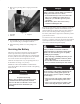
Adjusting the Traction Pedal
The traction pedal can be adjusted for operator comfort or
to reduce the maximum reverse speed of the machine.
1. Check the traction pedal stop adjustment. The pedal
stop (Fig. 47) should contact the frame slightly before
the pump reaches full stroke.
2. To adjust pedal stop, loosen jam nuts, push down on
traction pedal and tighten jam nuts when adjustment is
attained.
1
Figure 47
1. Traction pedal stop