
Operator's Manual


40
4. Start the engine and rotate the cam hex forward until the
front wheel starts to rotate, then rotate hex cam
backward until front wheel starts to rotate. Determine
the mid position of the neutral span and tighten the
retaining screw. Do procedure at low speed idle and at
high engine speed.
5. Tighten the screw securing the adjustment. Torque to
15–18 ft–lb (20–24 NSm)
6. Stop the engine.
7. Adjust the screw on the neutral return arm (Fig. 43)
until the gap between the end of the screw and the
switch contact is .090–.120 inch.
8. Remove the support blocks and lower the machine to
the shop floor. Test drive the machine to make sure it
does not move when the traction pedal is in neutral.
Adjusting the Parking Brake
Interlock Switch
1. Turn the engine off and remove the ignition key. Do not
engage the parking brake.
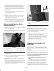
2. Remove knob from parking brake rod and screws from
steering tower cover (Fig. 44).
1
2
3
4
Figure 44
1. Steering tower cover
2. Parking brake knob/rod
3. Switch mounting screws
4. Cover mounting screws
3. Slide cover up steering shaft to expose parking brake
switch (Fig. 45).
4. Loosen screws and nuts securing parking brake switch
to left side of steering tower (Fig. 44).
5. Align parking brake rod paddle with switch plunger
(Fig. 45)
6. Press down on parking brake rod and push up on switch
until compressed length of switch plunger is .030”
(Fig. 45, inset) . This the distance between the brake rod
paddle and switch plunger housing.
.030”
1
2
Figure 45
1. Parking brake interlock
switch
2. Parking brake rod paddle
7. Tighten switch mounting screws and nuts.
8. With parking brake disengaged, the switch circuit
should have continuity. If there is no continuity, move
switch down slightly until there is continuity.
9. Check adjustment as follows:
• Engage the parking brake. Depress the traction pedal
while engine is running and the PTO lever is
disengaged. The engine should stop within 2 seconds. If
engine stops, the switch is operating correctly; thus,
continue operation. If engine does not stop, there is a
malfunction in the interlock system.
10. Install steering tower cover and brake rod knob.
Changing the Hydraulic Oil
And Filter
Initially, replace the hydraulic system filter after the first
full day’s operation — NOT TO EXCEED 10 HOURS.
Replace the filter after every 200 hours and oil after every
1500 hours.
The axle housing acts as the reservoir for the system. The
transmission and axle housing are shipped from the factory
with approximately 6 quarts (5.6 l) of high quality
hydraulic fluid. Check the level of hydraulic fluid before
the engine is first started and daily thereafter. The
recommended replacement fluid is:
Toro Premium Transmission/Hydraulic Tractor
Fluid
(Available in 5 gallon pails or 55 gallon drums. See
parts catalog or Toro distributor for part numbers.)
Alternate fluids: If the Toro fluid is not available, other
petroleum–based Universal Tractor Hydraulic Fluids
(UTHF) may be used provided its specifications fall within