
Service Manual


Mid-Size Walk Behind Service Manual 7 - 1
MOWER DECKS
Setting Up the Frame (Floating
Deck)
Checking Carrier Frame and Deck Alignment
1. Stop the engine, remove the key and disconnect
the spark plug wire(s) from the spark plug(s).
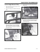
2. Place a long straight edge on top of the engine
deck as shown in Figure 146.
3. At the carrier frame cross tube, measure location
A height (Figure 146). This measurement must be
2-13/16 in. (71mm), plus or minus 1/4 in. (6mm).
4. If the height at location A is not correct,
adjustment is needed.
5. Loosen the carrier frame mounting bolts on both
sides of the machine (Figure 146).
6. Align the carrier frame and engine deck to obtain
2-13/16 in. (71mm), plus or minus 1/4 in. (6mm) at
location A (Figure 146).
7. Tighten the carrier frame mounting bolts on both
sides of the machine (Figure 146).
Figure 146
M-5315
Checking Engine Deck Height (Floating Deck)
1. Stop the engine, remove the key and disconnect
the spark plug wire(s) from the spark plug(s).
2. Adjust the tire pressure in all tires to
specifications.
3. Measure engine deck height at location A (Figure
147).
4. Measure engine deck height at location B (Figure
147).
5. If the height at location A and B are not the same,
change tire pressure slightly to make them the
same.
Figure 147
m-5237
Checking Carrier Frame Side-to-Side
1. Stop the engine, remove the key and disconnect
the spark plug wire(s) from the spark plug(s).
2. Adjust the tire pressure in all tires to
specifications.
3. Measure carrier frame height at location A (Figure
148).
4. Measure carrier frame height at location B (Figure
148).
(1) Carrier frame
(2) Top of engine deck
(3) Carrier frame mounting
bolts
(4) Location A, 2-13/16 in.
(71mm)± 1/4 in. (6mm)
(5) Straight edge
(6) Carrier frame cross tube
(1) Back view of machine
(2) Top of engine deck
(3) Tires
(4) Same height at locations
A and B