
Service Manual


HYDRAULIC DRIVE SYSTEMS
5 - 14 Mid-Size Walk Behind Service Manual
3. Hold OPC levers down.
Note: The OPC levers must be held down whenever
the speed control lever is out of the neutral position or
the engine will kill.
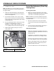
4. Adjust the right side linkage by turning the quick
track knob counterclockwise until the tire begins to
rotate forward (Figure 91).
5. Turn the knob clockwise 1/4 of a turn at a time.
Then move the speed control forward and back to
neutral. Repeat this until right wheel stops rotating
forward (Figure 91).
6. The
spring that keeps tension on the knob should
normally not need adjustment. However if
adjustment is needed, adjust the length of spring
to 1 in. (26mm) between the washers (Figure 91).
7. Adjust spring length by turning nut at front of
spring (Figure 91).
Figure 91
0610-19
Control Rod Adjustment (Pistol Grip
Floating Deck)
Checking Control Rod
1. With rear of machine supported on jack stands
and engine running at full throttle, move the speed
control lever to the medium speed position.
Note: The OPC levers must be held down whenever
the speed control lever is out of the neutral position or
the engine will kill.
2. Move the respective drive lever upward until it
reaches the neutral position and engage neutral
locks.
3. If the tire rotates in either direction, the length of
the control rod will need to be adjusted.
Adjusting Control Rods
1. Adjust the rod length by releasing the drive lever
and removing clevis pin. Rotate the rod in the rod
fitting (Figure 92).
2. Lengthen the rod if the tire is turning in reverse
and shorten the rod if the tire is turning forward.
3. Rotate the rod several turns if the tire is rotating
fast. Then, adjust the rod in 1/2 turn increments.
4. Release and engage neutral lock checking that
the tire does not rotate. Continue this process
until the tire does not rotate.
5. Place the hairpin back into clevis pin (Figure 92).
(A) Spring
(B) Hydro control linkage
(C) 1 inch (26 mm)
(D) Quick track knob
A
B
C
D