
Operator's Manual


15
6
5
3
5
6
3
m–5339
4
8
7
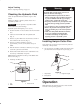
Figure 2
1. Bolt, 5/8 x 7/8 in.
(22.5 mm)
2. Lock washer, 5/16 in.
3. Washer, 5/16 in.
4. Stud
5. Spring
6. Locknut
7. Hose clamp
8. Fuel tank connection
3. Slide the hose clamp onto the fuel line (Fig. 2).
4. Push the fuel line onto the fuel tank connection and
secure it with a hose clamp (Fig. 2).
Installing Upper Handle
Important Install the flange bolts
(3/8 x 1 in. (26 mm)) with the bolt head on the inside of
machine frame. Refer to figure 3.
1. Align upper handle with upper mounting holes in rear
frame (Fig. 3).
2. Secure each upper mounting hole with a flange bolt
(3/8 x 1 in. (26 mm)) and flange nut (Fig. 3).
3. Select medium or low position for the lower mounting
hole (Fig. 3). This allows the upper handle to be
adjusted to the user’s height preference.
Note: Do not put in high position. Machine can not be
used in the high position.
4. Secure each lower mounting hole with a flange bolt
(3/8 x 1 in. (26 mm)) and flange nut (Fig. 3).
m–5401
1
2
3
4
5
6
7
8
9
Figure 3
1. Upper handle
2. Rear frame
3. Flange bolt, 3/8 x 1 in.
(26 mm)
4. Flange nut, 3/8 in.
5. Upper mounting hole
6. Lower mounting hole
7. Low position
8. Medium position
9. High position—Do not use
Installing Control Rods
1. Install control rod to drive lever and neutral lock using
a clevis pin (Fig. 4).
2. Install hairpin cotter between drive lever and neutral
lock and into clevis pin (Fig. 4).
Note: Make sure the clevis pin is inserted into the neutral
lock.
3. Repeat this procedure for the opposite side.