
Service Manual


ELECTRICAL
8 - 6 Mid-Size Walk Behind Service Manual
Figure 222
116-338
Figure 223 104-2541
Testing
1. Disconnect the switch from the wiring harness.
2. Verify that continuity exists between the terminals
listed for the switch position. Verify that there is
NO continuity between terminals not listed for
switch position. Note: the chart for the terminal
connections is also in the wiring diagram for each
model.
Electric PTO Clutch
Purpose
This clutch electrically controls the engagement and
disengagement of the Power Take Off (PTO) pulley.
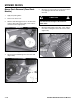
Location
The electric clutch is located on the PTO end of the
engine crankshaft (Figure 224).
Figure 224
mvc-067x
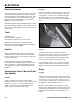
How It Works
The PTO clutch is composed of three major
components; the field, the clutch plate, and the friction
plate. The clutch plate always turns with the engine.
The field is a coil of wire on an iron core, which
becomes an electromagnet when power is applied.
The friction plate is the only piece that can slide up and
down on the crankshaft axis. It is normally spring
loaded so that it is not in contact with the clutch plate
and is pressed against the brake material opposite the
clutch. When power is applied, the friction plate is
drawn toward the clutch plate and two rotate as one.
OFF G + M
ON B + L
START B + L + S
OFF None
ON B + I + A X + Y
START B + I + S