
Operator's Manual


13
Set Up
Note: Determine the left and right sides of the machine
from the normal operating position.
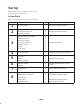
Loose Parts
Note: Use the chart below to identify parts for assembly.
Step Description Qty. Use
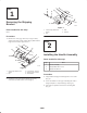
1
No parts needed – Removing the shipping bracket
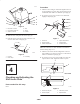
2
Handle assembly
Flanged bolt, 3/8 x 1 inch
Flange nut, 3/8 inch
1
4
4
Installing the handle assembly
3
Fuel tank with studs installed
Locknut, 5/16 inch
Bolt, 5/16 x 7/8 inch
Lock washer, 5/16 inch
Washer, 5/16 inch
Spring
Hose clamp
1
2
2
2
4
2
1
Installing the fuel tank
4
No parts needed – Checking and adjusting the shift lever
5
Clevis pin
Washer
Hairpin cotter pin
2
2
2
Installing the control rods
6
Hairpin cotter pin
Spacers
2
6
Installing the hairpin cotter pins and
spacers
7
Oil drain hose 1 Use for draining the engine oil
8
Operator’s Manual
Engine Operator’s Manual
Parts Catalog
Safety Video
Registration card
1
1
1
1
1
Read before operating machine
Read before operating machine
Watch before operating machine
Fill out and return to Toro