
Operator's Manual


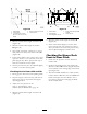
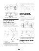


Figure 58
1. Caster Wheel 4. Height at locations A and B
2. Carrier Frame
5. Caster spacers
3. 1/4-3/8 inch (6-10 mm)
pitch over 24 inch (61 cm)
length
2. Measure car rier frame height at location A
( Figure 58 ).
3. Measure car rier frame height at location
B ( Figure 58 ).
4. T he height at location A m ust be a 1/4-3/8
inc h (6 mm -10 mm) lo w er than location B
( Figure 58 ).
5. If the car rier frame is not cor rect, mo v e caster
spacers to mak e it a 1/4-3/8 inc h (6 -10 mm)
pitc h ( Figure 58 ). Mo v e spacers from top or
bottom to mak e the cor rect pitc h.
6. T he tire pressure ma y also be adjusted slightly
to mak e a 1/4 inc h (6 mm) pitc h.
Checking Carrier Frame Side-to-Side
1. Diseng ag e the PTO and set the parking brak e .
2. Stop the engine , remo v e the k ey , and w ait for
all mo ving par ts to stop before lea ving the
operating position.
3. Adjust the tire pressure in all
tires to specifications; refer
to Dri v e System Maintenance , pag e 34
.
4. Measure car rier frame height at location A
( Figure 59 ).
Figure 59
1. Caster Wheel 4. Same height at locations A
and B
2. Carrier Frame
5. Caster spacers
3. Front height-of-cut pins
5. Measure car rier frame height at location B
( Figure 59 ).
6. If the car rier frame height is not the same
mo v e spacers from top or bottom of caster
wheel, to mak e it lev el. T he tire pressure ma y
also be adjusted slightly to mak e it lev el.
Checking the Mower Deck
Front-to-Rear Pitch
1. Chec k the tire pressure on both dec k and
traction unit.
2. P osition one blade front-to-rear ( Figure 60 ).
Measure at A and B locations ( Figure 60 ) from
a lev el surface to the cutting edg e of the blade
tips ( Figure 60 ).
3. T he mo w er blade should be 1/4 inc h (6 mm)
lo w er in front at A than in the rear at B . R otate
blades and re peat for other blades . If it is
not cor rect, proceed to Changing the Dec k
F ront-to-R ear Pitc h.
43