
Service Manual


HYDRAULIC DRIVE SYSTEMS
5 - 8 Mid-Size Walk Behind Service Manual
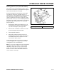
3. Select high, medium or low position for the lower
mounting hole (Figure 79). This allows the upper
handle to be adjusted to the user’s height
preference.
4. Secure each lower mounting hole with a flange
bolt (3/8 x 1 in. (26mm) and flange nut (Figure 79).
Torque bolts to 25 ft. lbs. (34 N-m).
Figure 79
m-5336
Install Control Rods
Before installing and adjusting control rods, loosen
quick release levers and move reference control bar all
the way forward.
Left Control Rod
1. Slide clevis pin through rod fitting and mounting
hole in control bracket (from outside). Secure with
washer and hairpin cotter (Figure 81).
2. Remove hairpin cotter and rod from upper control
bars (Figure 80).
3. Press and hold upper control bars against
reference bar, so stop hits (Figure 80).
Figure 80
m-5264
4. Push rod full forward until bearing is against
control bracket stop. Thread rod in or out of fitting
on control bracket until rod aligns with holes in
upper control bars (Figure 81).
5. When rod and holes in upper control bars line up,
turn rod one additional turn, so rod is shorter.
Note: Upper control bar stop must hit reference bar
before roller bearing hits control bracket stop.
(1) Upper handle
(2) Rear frame
(3) Flange bolt, 3/8 x 1 in.
(26mm)
(4) Flange nut, 3/8 in.
(5) Upper mounting hole
(6) Lower mounting hole
(7) Low position
(8) High position
(1) Upper control bars
(2) Hairpin cotter
(3) Reference bar
(4) Stop