
Operator's Manual


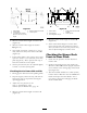


Figure 63
1. Measure blade at points A
and B
2. Measure from a level
surface
Changing the Deck
Front-to-Rear Pitch
Changing the front-to-rear pitc h is done b y
adjusting the front height-of-cut posts .
1. T o c hang e the front-to-rear pitc h, the front
height-of-cut posts can be adjusted ( Figure 64 ).
Figure 64
1. Caster Wheel
4. Jam nut
2. Carrier Frame
5. Ball joint
3. Front height-of-cut pins
2. T o raise the front of the dec k, loosen jam n ut
and rotate the front pin cloc kwise ( Figure 64 ).
3. T o lo w er the front of the dec k, loosen jam
n ut and rotate the front pin counter cloc kwise
( Figure 64 ).
4. P osition the blades front-to-rear . Measure at
C and D locations ( Figure 63 ) from a lev el
surface to the cutting edg e of the blades .
5. Chec k the side-to-side lev eling of the cutting
unit.
6. Tighten the jam n uts ( Figure 64 ).
Checking the Deck
Side-to-Side Leveling
1. Chec k the tire pressure on both dec k and
traction unit.
2. P osition the blades side-to-side ( Figure 65 ).
Measure at B and C locations ( Figure 65 ) from
a lev el surface to the cutting edg e of blade tips
( Figure 65 ).
Figure 65
1. Measure from a level
surface
2. Measure blade at points B
and C
3. T he difference betw een measurements B and
C should be no more than 1/4 inc h (6 mm).
Changing the Side-to-Side
Leveling
Changing the side-to-side lev eling is done b y
adjusting tire pressure .
44