
Operator's Manual


33
1
2
3
m–151
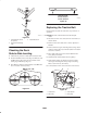
Figure 35
1. Cutting Edge
2. Curved Area
3. Wear/slot Forming
Checking for Bent Blades
1. Rotate the blades until the ends face forward and
backward (Fig. 36). Measure from a level surface to the
cutting edge, position A, of the blades (Fig. 37). Note
this dimension.
Front
m–1078
A
A
A
Figure 36
MEASURE FROM
CUTTING EDGE TO A
LEVEL SURFACE
m–2539
Figure 37
2. Rotate the opposite ends of the blades forward.
3. Measure from a level surface to the cutting edge of the
blades at the same position as in step 1. The difference
between the dimensions obtained in steps 1 and 2 must
not exceed 1/8 inch (3 mm). If this dimension exceeds
1/8 inch (3 mm), the blade is bent and must be replaced.
Refer to Installing the Blades on page 34.
A blade that is bent or damaged could break apart
and could seriously injure or kill you or
bystanders.
• Always replace bent or damaged blade with a
new blade.
• Never file or create sharp notches in the edges
or surfaces of blade.
Warning
Blades must be replaced if a solid object is hit, if the blade
is out of balance or is bent. To ensure optimum
performance and continued safety conformance of the
machine, use genuine TORO replacement blades.
Replacement blades made by other manufacturers may
result in non-conformance with safety standards.
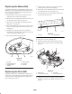
Hold the blade end using a rag or thickly-padded glove.
Remove the blade bolt, washer, anti-scalp cup and blade
from the spindle shaft (Fig. 38).
1
3
4
m–1082
2
5
Figure 38
1. Sail Area of Blade
2. Blade
3. Anti-scalp cup
4. Washer
5. Blade Bolt
Sharpening the Blades
1. Use a file to sharpen the cutting edge at both ends of the
blade (Fig. 39). Maintain the original angle. The blade
retains its balance if the same amount of material is
removed from both cutting edges.