
Service Manual


Mid-Size Walk Behind Service Manual 8 - 11
ELECTRICAL
Hourmeter
Purpose
The hourmeter is present to give an indication of
operating hours. It is standard on some models an
optional on others.
On some models it is connected between the clutch
switch and clutch. In that instance it will measure clutch
operating time not engine hours.
In other models it is connected between the alternator
and clutch switch. In this situation it will receive power
whenever the engine is running.
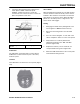
Location
The hourmeter is located in the control panel (Figure
232).
Figure 232
mvc-063
How It Works
Since a normal clock might be affected by variations in
voltage and current, the hourmeter is made up of a
combination of an electric "winder" and a mechanical
clock movement. When power is applied, a coil is
energized to wind the movement. The movement
unwinds in about 2 seconds. As it finishes its rotation,
it re-energizes the coil so that the cycle can start over.
Testing
Verify that 12 volts is present across the two terminals
when the engine is running. If so, and the meter is not
running, replace the meter. If 12 volts is not present,
check the connections back towards the alternator or
battery.
Switch (65-7410 & 1-513051)
Purpose
This switch is used in both the parking brake and
transmission linkage. The switch is activated as the
linkage to these components is engaged or
disengaged.
Location
The location depends on the application. A parking
brake switch application will be located in or near the
brake linkage. The same applies with a transmission
neutral application.
Common locations are on or under the traction frame
and under the control panel. Activate the linkage in
question and follow it, looking for the switch shown in
Figure 233.
Figure 233
mvc-053
Testing
This is a normally open switch; when it is out in your
hand there should be no continuity between the
terminals. Use a ohmmeter to determine if the contacts
open and close correctly.