
Service Manual


26
BDP-10A/16A/21L
REMOVAL, INSPECTION AND AS-
SEMBLY OF THE END CAP AND
VALVE PLATE BDP-21L
Refer to figure 24.
Disassembly BDP-21L
1. Using any combination of two, 9/16” wrenches
or 9/16” socket and rachet drive, loosen the end
cap bolts (58) evenly.
2. Keeping the end cap (25) held in place re-
move the four end cap bolts (58).
3. Slowly remove the end cap (25).
4. Remove the valve plate (29).
5. Remove housing alignment pins (26).
6. Remove housing gasket (28).
Inspection BDP-21L
1. Inspect the end cap (25) body for damage,
nicks or unusual wear patterns. Replace if nec-
essary.
2. Inspect the bronze side of the valve plate
(29). The running surface may show evidence
of minor abrasive rings.
This is normal. Grooving in the plate, or material
transfer that is evident when the surface is
checked by dragging a fingernail across it, would
be cause for replacement of the valve plate.
3. Inspect and replace alignment pins (26) if bent
or distorted.
4. Replace the housing O-ring (28) with a new
O-ring before reassembly.
Assembly BDP-21L
1. Install housing O-ring (28) into housing O-ring
seat in housing (15).
2. Install alignment pins (26) into housing (15).
3. Lubricate the valve plate prior to installation.
Install valve plate (29) with the bronze side down,
contacting the cylinder block.
4. Install end cap (25). Before installing the four
end cap bolts (58), push down on end cap (25)
verifying alignment and insuring that the cylinder
block pistons spring back and fourth. Install end
cap bolts. Tighten, per Table 6, page 16, torque
values.
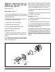
Figure 24. BDP-21L
41
39
56 x2
44
58 x4
25
29
28
26
15
26
40