
Operator's Manual


Servicing the Caster Wheel
and Bearings
T he caster wheels rotate on a roller bearing
suppor ted b y a spanner bushing . If the bearing is
k e pt w ell lubricated, w ear will be minimal. F ailure
to k ee p the bearing w ell lubricated will cause rapid
w ear . A w obbly caster wheel usually indicates a
w or n bearing .
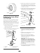
1. R emo v e the loc kn ut and wheel bolt holding
the caster wheel to the caster fork ( Figure 59 ).
Figure 59
1. Locknut 4. Spanner Bushing
2. Wheel Bolt 5. Roller Bearing
3. Bushing
2. R emo v e one bushing, then pull the spanner
bushing and roller bearing out of the wheel
hub ( Figure 59 ).
3. R emo v e the other bushing from the wheel hub
and clean any g rease and dir t from the wheel
hub ( Figure 59 ).
4. Inspect the roller bearing, bushings , spanner
bushing and inside of the wheel hub for
w ear . R e place any defecti v e or w or n par ts
( Figure 59 ).
5. T o assemble , place one bushing into the wheel
hub . Grease the roller bearing and spanner
bushing and slide them into the wheel hub .
Place the second bushing into the wheel hub
( Figure 59 ).
6. Install the caster wheel into the caster fork
and secure with the wheel bolt and loc kn ut.
Tighten the loc kn ut until the spanner bushing
bottoms ag ainst the inside of the caster forks
( Figure 59 ).
7. Grease the fitting on the caster wheel.
Adjusting the Electric Clutch
T he clutc h is adjustable to ensure proper
eng ag ement and proper braking . Chec k
adjustment after ev er y 100 hours of operation.
1. Inser t a 0.015–0.021 inc h (0.381–0.533 mm)
feeler g aug e through one inspection slot in the
side of the assembly . Mak e sure it is betw een
the ar mature and the rotor friction surfaces .
2. Tighten the loc k n uts until there is slight
binding on the feeler g aug e but it can be
mo v ed easily within the air g ap ( Figure 60 ).
3. R e peat this for the remaining slots .
4. Chec k eac h slot ag ain and mak e slight
adjustments until the feeler g aug e betw een the
rotor and ar mature with v er y slight contact
betw een them.
Figure 60
1. Adjusting nut 3. Feeler gauge
2. Slot
Cooling System
Maintenance
Cleaning the Air Intake
Screen
Before eac h use remo v e any build-up of g rass , dir t
or other debris from the cylinder and cylinder head
cooling fins , air intak e screen on flywheel end, and
carburetor -g o v er nor lev ers and linkag e . T his will
45