
Operator's Manual


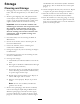


Figure78
1.CarrierFrame4.LocationA,1-5/16inch
(33mm)±1/4inch(6mm)
2.Topofenginedeck5.Straightedge
3.Carrierframemounting
bolts
6.Carrierframecross
channel
CheckingtheEngineDeckHeight
1.DisengagethePTOandsettheparkingbrake.
2.Stoptheengine,removethekey,andwaitforall
movingpartstostopbeforeleavingtheoperating
position.
3.Adjustthetirepressureinthereartiresto
specications;refertoDriveSystemMaintenance
,page35.
4.MeasureenginedeckheightatlocationA(Figure79).
Figure79
1.Backviewofmachine
3.Tires
2.Topofenginedeck4.Sameheightatlocations
AandB
5.MeasureenginedeckheightatlocationB(Figure79).
6.IftheheightatlocationAandBarenotthesame,
changetirepressureslightlytomakethemthesame.
CheckingtheCarrierFrame
Front-to-RearPitch
Thecarrierframemusthaveapitchbetween1/8inch
(3mm)to3/8inch(9mm)overthelengthof24inches
(61cm)onthecarrierframe(Figure80).
1.Measureout24inches(61cm)onthecarrierframe
(Figure80).
Figure80
1.CarrierFrame
4.HeightatlocationsAand
B
2.1/8inch-3/8inch(3-10
mm)pitchover24inch(61
cm)length
5.CasterWheel
3.24inches(61cm)6.Casterspacers
2.MeasurecarrierframeheightatlocationA
(Figure80).
3.MeasurecarrierframeheightatlocationB
(Figure80).
4.TheheightatlocationAmustbean1/8-3/8inch(3
mm-10mm)lowerthanlocationB(Figure80).
5.Ifthecarrierframeisnotcorrect,movecaster
spacerstomakeitan1/8-3/8inch(3-10mm)pitch
(Figure80).Movespacersfromtoporbottomto
makethecorrectpitch.
6.Thetirepressuremayalsobeadjustedslightlyto
makean1/8-3/8inch(3-10mm)pitch.
54