
Operator's Manual


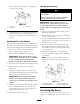


the component or circuit for a malfunction or
shor t. Pull out on the fuse to remo v e or re place
it ( Figure 42 ).
Figure 42
1. Fuse, 25 amp, blade type 2. Fuse, 30 amp, blade type
Drive System
Maintenance
P erfor m the follo wing linkag e adjustments when
the mac hine needs maintenance . P erfor m ste ps
Adjust the Speed Control Linkag e through
Adjusting the T rac king . If and adjustment is
needed , do them in the order that they are listed.
Adjusting the Speed Control
Linkage
1. Diseng ag e the PTO and set the parking brak e .
2. Stop the engine and w ait for all mo ving par ts
to stop before lea ving the operating position.
3. Mo v e the speed control lev er (located on
the console) to the full forw ard position
( Figure 43 ).
Figure 43
1. Speed control lever 4. Medium speed position
2. Full speed position 5. Control panel
3. Neutral position
4. Chec k the orientation of the tabs on the ends
of the speed control crank. T hese tabs should
be pointing straight do wn at the 6 o’cloc k
position appro ximately ( Figure 44 ).
5. If adjustment is needed, loosen the n uts on
both sides of the swi v el on the speed control
rod ( Figure 44 ).
6. Adjust the swi v el until the tabs are at the
6 o’cloc k position ( Figure 44 ).
7. Tighten the n uts on both sides of the swi v el
( Figure 44 ).
37