
Service Manual


Repairs
Axle Removal and Installation
1. Disconnect the battery cable from the negative (–)
battery post.
2. Remove the cutting unit from the suspension frame.
Remove the cutting unit suspension frame from the
traction unit. (See the Repairs section of Chapter 12 -
Cutting Units.)
3. Remove the fuel tank. (See Removing and Installing
the
Fuel Tank in the Fuel System Repairs section of
Chapter 3 - Mitsubishi Diesel Engine.)
4. Remove the hydrostatic transmission. (See Hydro-
s
tatic Transmission Removal and Installation in the
Repairs section of Chapter 4 - Hydraulic System.) Cap
Figure 3A
or plug all hydraulic lines and fittings to prevent oil
co
ntamination.
5. Remove the carrier brackets (Fig. 3A).
6. Slightly loosen all of the front wheel lug nuts.
7. Jack both of the front wheels off of the ground and
in
stall jackstands or blocks under the traction unit frame
(not the axle tubes) to prevent the machine from falling.
8. Remove both of the front wheels.
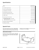
9. If unit is equipped with 4WD, remove nut (Fig. 3B,
Item 47), washer (Item 27) and flange (Item 26) from
differential axle pinion (Item 12). Use Differential Gear
26
27
47
Apply Permatex No. 2 to
splines when installing
flange to pinion.
12
Holder tool to hold gears when removing nut.
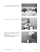
10. Put a jack or blocking under the differential to hold
Figu
re 3B
it in place. Remove the cap screws and lock nuts
securing the axle mounting pads to the frame. Carefully
lower the differential axle and pull it out from under the
traction unit.
Installation
NOTE: Before installing flange (for 4WD drive shaft),
apply
Permatex No. 2 to external splines of pinion and
internal splines of flange. Tighten lock nut to secure
pinion coupler 75 - 90 ft-lb (102 - 122 N-m)..
1. To install axle, reverse steps 1 - 10 above. Be sure to
refill
the differential with the proper oil before operation.
2. Check the engine to transmission coupler alignment.
(See Drive Coupling Alignment in the Adjustments sec-
tion of Chapter 10 - Engine to Transmission Coupler.
Groundsmaster
®
220-D/223-D Page 6 - 3
Rev. G
Repairs