
Operator's Manual


21
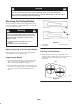
4. Torque blade bolt to 75–80 ft. lb. (101–108 Nm).
m–3779
1
4
3
2
4
6
5
Figure 21
1. Blade
2. Blade bolt
3. Cone washer
4. Spacer
5. Thin washer
6. Nut
Adjusting the Axle Height
Desired height-of-cut range can be obtained by adjusting
the rear axle and placing caster spacers above or below the
caster arm (see chart).
1. Stop engine and remove spark plug wire(s).
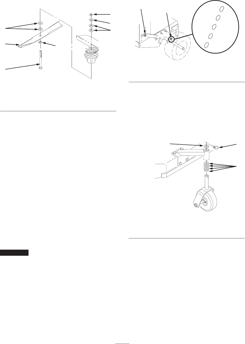
2. Loosen but do not remove the 2 axle pivot bolts and the
2 axle adjustment bolts (Fig. 22).
3. Place a jack under the rear center of the engine frame.
Raise the back end of the engine frame up enough to
remove front 2 axle adjustment bolts (Fig. 22).
4. Raise or lower the engine frame with the jack,so that
front 2 axle adjustment bolts can be installed in the
desired hole location (Fig. 22). A tapered punch can be
used to help align the holes.
5. Tighten all 4 bolts and lower the unit.
6. Adjust control rods and brake linkages as required.
Refer to Servicing the Brake on page 30 and Installing
the Traction Control Rod on page 14.
Important It will be necessary to adjust control rods
and brake linkage when changing axle positions for proper
traction and brake function.
m–3789
1
2
A
B
C
D
E
Figure 22
1. Axle pivot bolt 2. Axle adjustment bolt
Adjusting the Caster Position
1. Using the height-of-cut chart, adjust the caster spacers
to match with the axle hole selected (Fig. 23).
2. Remove clevis pin, slide caster from support and
change spacers (Fig. 23).
3. Install caster in support and insert clevis pin (Fig. 23).
m–3791
1
3
2
Figure 23
1. Clevis pin
2. Spacer, 3/16 in. (5 mm)
3. Spacer, 1/2 in. (13 mm)