
Service Manual


HYDRAULIC DRIVE SYSTEMS
5 - 10 Mid-Size Walk Behind Service Manual
Hydro Linkage Adjustments (Pistol
Grip Floating Deck)
Perform the following linkage adjustments when
the machine needs maintenance. If adjustment is
needed, do them in the order that they are listed
.
• Adjust speed control linkage.
• Adjust neutral control linkage.
• Adjust hydro control linkage.
• Adjust control rods.
• Tracking adjustment.
Speed Control Linkage (Pistol Grip
Floating Deck)
1. Stop engine and wait for all moving parts to stop.
2. Move the speed control lever (located on the
console) to the full forward position.
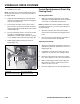
3. Check the orientation of the tabs on the ends of
the speed control crank. These tabs should be
pointing straight down at the 6 o’clock position
approximately (Figure 83).
4. Adjust the threaded yoke at the bottom of the
speed control linkage until the tabs are at the 6
o’clock position (Figure 83).
Figure 83
m-5398-1
5. Pull the speed control lever back to neutral.
6. Check to make sure the safety switch is
depressed and there is a 5/16 in. (8mm) space
between the actuating tab and the switch. (Figure
84).
7. If needed, adjust switch location to create the 5/16
in. (8mm) space (Figure 84).
Figure 84
m-5394-1
Figure 85 0610-03
(1) Speed control rod
(2) Yoke
(3) Speed control crank
(4) Tabs, 6 o’clock position
(5) Jam nut
(1) Actuating tab
(2) 5/16 in (8mm) space
(3) Safety switch
(A) Tab at 6 o’clock
A