
Service Manual


HYDRAULIC DRIVE SYSTEMS
5 - 24 Mid-Size Walk Behind Service Manual
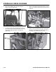
3. Remove upper hydraulic line from wheel motor
and attach to flow test gauge (Figure 108).
Figure 108
mvc-893
4. Remove lower hydraulic line from wheel motor
and attach to the other side of the flow test
gauge(Figure 109).
Figure 109
mvc-890
Note: When using a flow test gauge that is
NOT bi-directional and it is connected in this
manner, it is important not to operate the
machine in reverse or you could damage the
flow test gauge.
Figure 110
mvc-890
5. Open the restriction valve all the way
(counterclockwise) (Figure 111).
Figure 111
mvc-894
R
e
v
e
r
s
e
R
e
v
e
r
s
e
F
o
r
w
a
r
d
F
o
r
w
a
r
d