
Service Manual


ELECTRICAL
8 - 2 Mid-Size Walk Behind Service Manual
Electrical Systems
This manual covers a variety of machines. From recoil
start models with simple electrical systems to electric
start models with an electric blade clutch. Some of the
electrical components are used in different ways in
different models. It is important you use the wiring
diagram for your specific model.
We will start by identifying the individual parts, locating
them and providing testing procedures. At the back of
this section is a wiring diagram for each model covered
in this manual.
Tools
Volt Ohm meter.
Flat and Phillips screwdrivers.
Box and open end wrenches of various sizes.
Additional information can be found in the LCE
Electrical Troubleshooting CD #492-4757, available
through your Toro parts supplier.
Caution
Before performing any tests with a continuity light or
ohmmeter, disconnect the component from the wire
harness. This ensures you are testing the component,
not some other circuit.
Interlock modules and delay modules MUST be
removed from the circuit before performing any tests
with an ohmmeter or continuity light. Battery voltage
can damage these modules if applied to the wrong
terminals.
Servicing the Fuse (T-Bar and Pistol
Grip Models)
Purpose
Fuses are used in several of the circuits to limit
damage in the event of excessive current flow. If a fuse
fails look for a short circuit or any component that
appears to have been overheated. A failed fuse is
usually a sign of a problem in that circuit.
Location
Fuses are located in a variety of places on the various
models. The first places to look should be under the
control panel or on the chassis alongside the engine.
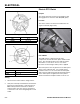
Most will be found in one of those two places. One
location is shown here, under the control panel (Figure
213).
Figure 213
MVC-075
Testing
A failed fuse will often be discolored or melted.
However, not all failures are easy to see. A fuse can be
checked with a continuity tester if there is doubt. If
there is no continuity between the terminals, replace
the fuse, even if it appears good (Figure 213).
Fuse: blade-type. There are 7, 5, 10, 20, 25 and 30
amp fuses used in these models. Refer to the wiring
diagram for your model to determine the proper size.
Relay
Purpose
A relay is an electrically operated switch. An electrical
current is sent to the relay which can be used to control
more than one circuit. It can turn a circuit on or off or
turn one circuit on and another off at the same time. It
all depends on which terminals are used.
We have at least 3 different part numbers of relays.
However, they all work the same and are tested in the
same manner. The difference is in the method used to
mount them and the amount of amperage they can
handle.