
Operator's Manual


34
Adjusting Mower Belt Tension
Service Interval/Specification
Check belt tension after the first 8 and 25 hours of
operation. Check the belt tension every 50 hours.
Important Belt must be tight enough to not slip during
heavy loads while cutting grass. Over tensioning will
reduce belt and spindle bearing life.
1. Disengage the blade control (PTO), set the parking
brake and stop the engine.
2. Loosen locknut on turnbuckle (Fig. 49).
3. Rotate turnbuckle toward rear of mower to increase
tension on belt. Rotate turnbuckle toward front of
mower to decrease tension on belt (Fig. 49).
Note: The eyebolt threads on both ends of the turnbuckle
should be engaged a minimum of 5/16 in. (8 mm).
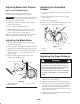
Adjusting the Blade Brake
1. Disengage the blade control (PTO), set the parking
brake and stop the engine.
2. If necessary, adjust the spring mounting bolts so that the
blade brake pad rubs against the pulley edges (Fig. 50).
3. Adjust the nut at the end of the blade brake rod until
there is 1/8–3/16 in. (3–5 mm) between the nut and
spacer (Fig. 50).
4. Engage the blades. Ensure the blade brake pad no
longer contacts the pulley edges.
m–47271
2
3
Figure 50
1. Spring mounting bolts
2. Blade brake pad
3. 1/8–3/16 in. (3–5mm)
Adjusting the Grass/Mud
Scraper
1. Loosen the locknut holding scraper to the engine frame
(Fig. 51).
2. Rotate scraper until they align with center of pulley
grooves (Fig. 51).
3. Tighten the locknut (Fig. 51).
Note: The scraper must not contact the pulley on the sides
or bottom of grooves. Re-adjust if necessary.
2
3
1
m–3776
Figure 51
1. Scraper
2. Locknut
3. Pulley
Replacing the Grass Deflector
An uncovered discharge opening could allow the
lawn mower to throw objects in the operator’s or
bystander’s direction and result in serious injury.
Also, contact with the blade could occur.
Never operate the lawn mower unless you install a
cover plate, a mulch plate, or a grass chute and
catcher.
Warning
1. Remove the locknut, bolt, spring and spacer holding
deflector to the mounts (Fig. 52).
2. Straighten deflector mounts if they are bent (Fig. 52).
3. Install new deflector between mounts with spacer and
spring. Hook the front end of the spring around the
front deflector mount. Insert bolt through spacer and
secure with locknut. Confirm there is downward spring
force on deflector (Fig. 52).
4. Tighten the bolt and locknut until they lightly contact
the pivot brackets (Fig. 52).