
Operator's Manual


17
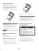
4. If clearance is not correct, loosen shift lever plate and
adjust it side–to–side. Tighten the shift lever plate.
4
Rear View
1
4
3
2
2
m–7454
Figure 11
1. Shift lever, 2nd gear
2. Shift lever plate
3. Shift lever, neutral
4. Equal distance
Mounting the Fuel Tank
1. Align fuel tank with the top of the rear frame (Fig. 12).
2. Secure the right side of the fuel tank to the rear frame
with 2 bolts (5/16 x 7/8 inch), lock washers (5/16 inch)
and washers (5/16 inch) (Fig. 12).
3. Secure the left side of the fuel tank to the rear frame
with 2 studs, washers (5/16 inch), springs and locknuts
(5/16 inch) (Fig. 12).
Note: Tighten left side of the fuel tank until it is completely
tight and then unscrew locknut one full turn. This will
allow the spring to work.
m–3771
1
2
3
5
4
6
3
Figure 12
1. Bolt, 5/16 x 7/8 inch
2. Lock washer, 5/16 inch
3. Washer, 5/16 inch
4. Stud
5. Spring
6. Locknut
4. Slide the hose clamp onto the fuel line (Fig. 13).
5. Push the fuel line onto the fuel tank connection and
secure it with a hose clamp (Fig. 13).
3
2
1
m–6442
Figure 13
1. Fuel line
2. Hose clamp
3. Fuel fitting
Installing the Muffler
1. Loosen the clamp (Fig. 14).