
Operator's Manual

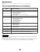


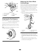

Figure40
1.Controlrodandtting
5.Washer
2.3-1/2inch(89mm)
6.Hairpincotterpin
3.Idlerbracket
7.Rodtting
4.Clevispin
8.HoleF
CheckingtheTirePressure
ServiceInterval:Every50hours/Monthly(whichever
comesrst)—Checkthetirepressure
Checkthepressureatthevalvestem(Figure41).
Maintaintheairpressureinthereartiresat12-14psi
(83-97kPa).Uneventirepressurecancauseanuneven
cut.
Note:Thefronttiresaresemi-pneumatictiresanddo
notrequireairpressuremaintenance.
Figure41
ReplacingtheCasterWheel
ForkBushings
Thecasterwheelforksaremountedinbushingspressed
intothetopandbottomofthecarrierframemounting
pivottubes.Tocheckthebushings,movethecaster
forksbackandforthandside-to-side.Ifacasterforkis
loose,thebushingsarewornandmustbereplaced.
1.Raisethecuttingunitsothecasterwheelsareoff
theoor,thensupportthefrontofthemowerwith
jackstands.
2.Removethelockingpinandspacer(s)fromthetop
ofthecasterwheelfork(
Figure42).
Figure42
1.LockingPin
3.Carrierframepivottube
2.Spacers4.Casterwheel
3.Pullthecasterwheelforkoutofthemountingtube,
leavingthespacer(s)onthebottomofthefork.
Rememberthelocationofthespacersoneachfork
toensurecorrectinstallation,andtomaintainalevel
deck.
4.Insertapinpunchintothemountingtubeand
carefullydriveoutthebushings(
Figure43).Clean
theinsideofthemountingtube.
30