
Operator's Manual


FrameSetup
CheckingtheCarrierFrameandEngine
DeckAlignment
Note:MisalignmentcancauseexcesswearonthePTO
drivebelt.
1.DisengagethePTOandsettheparkingbrake.
2.Stoptheengine,removethekey,andwaitforallmoving
partstostopbeforeleavingtheoperatingposition.
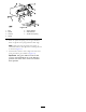
3.Placealongstraightedgeontopoftheenginedeckas
showninFigure62.
4.Atthecarrierframecrosschannel,measuretheheight
atlocationA(Figure62).
Note:Thismeasurementshouldbe33mm(1-5/16
inch),plusorminus6mm(1/4inch).
5.IftheheightatlocationAisnot33mm(1-5/16inch),
anadjustmentisneeded.
6.Loosenthecarrierframemountingboltsonbothsides
ofthemachine(Figure62).
7.Alignthecarrierframeandenginedecktomatch33
mm(1-5/16inch),plusorminus6mm(1/4inch)at
locationA(Figure62).
8.Tightenthecarrierframemountingboltsonbothsides
ofthemachine.
Figure62
1.Carrierframe4.LocationA,33mm(1-5/16
inch),plusorminus6mm
(1/4inch)
2.Topofenginedeck5.Straightedge
3.Carrierframemounting
bolts
6.Carrierframecross
channel
CheckingtheEngineDeckHeight
1.DisengagethePTOandsettheparkingbrake.
2.Stoptheengine,removethekey,andwaitforallmoving
partstostopbeforeleavingtheoperatingposition.
3.Adjustthetirepressureinthereartirestospecications;
refertoDriveSystemMaintenance(page30).
4.MeasuretheenginedeckheightatlocationA(Figure
63).
Figure63
1.Backviewofmachine
3.Tires
2.Topofenginedeck4.Sameheightatlocations
AandB
5.MeasuretheenginedeckheightatlocationB(Figure
63).
6.IftheheightatlocationAandBarenotthesame,
changetirepressureslightlytomakethemthesame.
CheckingtheCarrierFrame
Front-to-RearPitch
Thecarrierframemusthaveapitchbetween3mm(1/8inch)
to9mm(3/8inch)overthelengthof61cm(24inches)on
thecarrierframe(Figure64).
1.Measureout61cm(24inches)onthecarrierframe
(Figure64).
41