
Operator's Manual


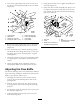


2.Loosentheupperangebolts(3/8x1inch)and
theangenutsecuringthehandletotherearframe
(Figure18).
Figure18
1.Upperhandle5.Uppermountinghole
2.Rearframe
6.Lowermountingholes
3.Flangenut,(3/8inch)
7.Lowposition
4.Flangebolt,(3/8x1inch)
8.Highposition
3.Removethelowerangebolts(3/8x1inch)and
angenutssecuringthehandletotherearframe
(
Figure18).
4.Pivotthehandletothedesiredoperatingposition
andinstallthelowerangebolts(3/8x1inch)and
theangenutsintothemountingholes.Tighten
allangebolts.
5.Checkthecontrolbarforcorrectadjustment.Refer
toAdjustingtheControlBarinthemaintenance
section.
6.Checktheparkingbrakeadjustment.Referto
CheckingtheBrakesinthemaintenancesection.
AdjustingtheFlowBafe
Themowerdischargeowcanbeadjustedfordifferent
typesofmowingconditions.Positionthecamlockand
bafetogivethebestqualityofcut.
1.DisengagethePTO,movethemotioncontrol
leverstotheneutrallockedpositionandsetthe
parkingbrake.
2.Stoptheengine,removethekey,andwaitforall
movingpartstostopbeforeleavingtheoperating
position.
3.Toadjustthecamlock,swingtheleveruptoloosen
thecamlock(Figure19).
4.Adjustthebafeandcamlockintheslottothe
desireddischargeow.
5.Swingtheleverbackovertotightenthebafeand
camlock(Figure19).
6.Ifthecamdoesnotlockthebafeintoplaceoritis
tootight,loosentheleverandthenrotatethecam
lock.Adjustthecamlockuntilthedesiredlocking
pressureisachieved.
Figure19
1.Camlock4.Slot
2.Lever5.Rotatethelevertorelease
orlockthecam
3.Rotatecamtoincreaseor
decreaselockingpressure
19