
Operator's Manual


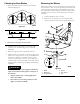

Figure51
1.Hydrauliclter
3.Adapter
2.Gasket
6.Applyathincoathydrouidtotherubbergasketon
thereplacementlter.
7.Installreplacementhydrauliclterontothelter
adapter.Donottighten.
8.Removeplasticbagfromreservoiropeningandallow
ltertollwithhydraulicuid.
9.Whenthehydrauliclterisfull,turntheoillter
clockwiseuntiltherubbergasketcontactsthelter
adapter,thentightenthelteranadditional1/2turn
(
Figure51).
10.Cleanupanyspilleduid.
11.Ifthereisnouid,addMobil115W-50synthetic
motoroilorequivalentsyntheticoiltoapproximately6
mm(1/4inch)belowthetopofreservoirbafe.
Important:Useoilspeciedorequivalent.Other
uidscouldcausesystemdamage.
12.Startengineandletrunforabouttwominutestopurge
airfromthesystem.Stoptheengineandcheckfor
leaks.Ifoneorbothwheelswillnotdrive,referto
BleedingHydraulicSystem.
13.Rechecklevelandadduid,ifrequired.Donotoverll.
BleedingtheHydraulicSystem
Thetractionsystemisselfbleeding,however,itmaybe
necessarytobleedthesystemifuidischangedorafterwork
isperformedonthesystem.
Purgetheairfromthehydraulicsystemwhenanyhydraulic
components,includingoillter,areremovedoranyofthe
hydrauliclinesaredisconnected.Thecriticalareaforpurging
airfromthehydraulicsystemisbetweentheoilreservoir
andeachchargepumplocatedonthetopofeachvariable
displacementpump.Airinotherpartsofthehydraulicsystem
willbepurgedthroughnormaloperationoncethecharge
pumpisprimed.
1.DisengagethePTOandsettheparkingbrake.
2.Stoptheengineandwaitforallmovingpartstostop
beforeleavingtheoperatingposition.
3.Raisetherearofthemachineupontojackstandshigh
enoughtoraisethedrivewheelsofftheground.
4.Checkthehydraulicuidlevel.
5.Starttheengineandmovethethrottlecontroltothe
fullthrottleposition.Movethespeedcontrolleverto
themiddlespeedpositionandplacethedrivelevers
intothedriveposition.
Ifeitherdrivewheeldoesnotrotate,itispossible
toassistthepurgingofthechargepumpbycarefully
rotatingthetyreintheforwarddirection.
Note:Itisnecessarytolightlytouchthechargepump
capwithyourhandtocheckthepumptemperature.If
thecapistoohottotouch,turnoffengine.Thepumps
maybedamagedifthepumpbecomestoohot.Ifeither
drivewheelstilldoesnotrotatecontinuetonextstep.
Figure52
1.Socketheadscrew2.Chargepumpcap
6.Thoroughlycleantheareaaroundeachofthecharge
pumphousings.
7.Toprimethechargepump,loosentwohexsocket
headcapscrews(Figure52)1-1/2turnsonly.Make
sureengineisnotrunning.Liftchargepumphousing
upwardandwaitforasteadyowofoiltoowout
fromunderhousing.Retightencapscrews.Dothisfor
bothpumps.
Note:Hydraulicreservoircanbepressurizedtoupto
5psi(0.35bar)tospeedthisprocess.
8.Ifeitherdrivewheelstilldoesnotrotate,stopand
repeatsteps4and5ontherespectivepump.Ifwheels
rotateslowly,thesystemmayprimeafteradditional
running.Recheckhydraulicuidlevel.
9.Allowunittorunseveralminutesafterthecharge
pumpsareprimedwithdrivesysteminthefullspeed
position.
10.Checkthehydrocontrollinkageadjustment.Referto
AdjustingtheHydroControlLinkages.
38