
Operator's Manual


6.Ifthereisnoadjustmentleftintheturnbuckleand
thebeltisstillloose,therearidlerpulleyneedstobe
positionedtothemiddleorfronthole(Figure47).
Usetheholethatwillgivethecorrectadjustment.
7.Whentheidlerpulleyismovedthebeltguidemust
bemoved.Movethebeltguidetothefrontposition
(Figure47).
Figure47
1.Rearidlerpulley4.Beltguideinbackposition
2.Middlehole
5.Frontidlerpulley(48inch
mowerdeckonly)
3.Fronthole
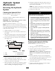
8.Checkthebeltguideundertheengineframefor
properadjustment(Figure48).
Note:Thedistancebetweenthebeltguideand
themowerbeltshouldbe3/4inch(19mm)when
youengagethemowerbelt(Figure48).Adjustthe
mowerbeltguideasnecessary.Thedisengagedbelt
shouldnotdragorfalloffthepulleywhentheguides
areproperlyadjusted.
Figure48
1.Beltguide
9.Checkthebladebrakeadjustment;refertoAdjusting
theBladeBrake.
AdjustingthePTOEngagement
Linkage
ThePTOengagementlinkageadjustmentislocated
beneaththefrontlefthandcorneroftheenginedeck.
1.Disengagethebladecontrol(PTO)leverandsetthe
parkingbrakes.
2.Stoptheengineandwaitforallmovingpartstostop
beforeleavingtheoperatingposition.
3.Engagethebladecontrollever(PTO).
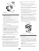
4.Adjustthelinkagelengthtowherethelowerend
ofthebellcrankjustclearstheaxlesupportgusset
(Figure49).
Figure49
1.Bellcrank4.Yoke
2.Safetyswitchlocated
underenginedeck
5.Nut
3.Bellcrankjustclearsthe
gussetwiththePTO
engageded
6.Assistarmlink
5.Makesuretheassistarmisagainsttherearassistarm
stoponthedeck(Figure50).
6.Pushthebladecontrollever(PTO)downtothe
disengagedposition.
7.Theassistarmshouldcontactthefrontassistarm
stoponthedeck.Ifitdoesnotcontact,adjustthe
bellcranksoitisclosertothegusset(Figure50).
37