
Service Manual


Plunger Style Zone Start Brake Operation
(cont'd)
The kill switch is a
two
position push button-typeswitch
that is closed when the control bar is more than
10
cm
(4”)
below the handle and open when
it
is closer than
10
cm
(4').
The body of the switch is grounded to the
engine while the terminal on the switch is connected
to the ignition coil kill wire. When the switch is open,
the coil will produce spark. When closed, the ignition
coil is grounded and spark is inhibited. The switch is
actuated by a small arm coming from the brake disk.
The brake mechanism is simply a bracket, a spring and
a brake disk. When the control bar is near the handle,
the spring is compressed and the disk is pulled away
from the bottom of the flywheel. When the control bar
,is released, the spring forces the disk into the flywheel
and helps the engine stop within the required three
seconds.
Plunger Style Zone Start Brake Disassembly
1.
Remove the spark plug wire to prevent acci-
2.
Before removing the plunger style brake from the
engine, remove any components necessary to
get a clear view of the brake. Operate the brake
while inspecting for proper flywheel to brake disk
contact and proper operation of the switch.
Repair or replace parts as necessary.
3.
Remove the ignition coil kill wire from the switch
and check using an ohmmeter or test
light.
When
the control bar is down, the switch should be
closed. When the control bar is
10
cm
(4”)
below
the handle the switch should move from closed
to open and should remain open until the control
bar is brought all the way up to the handle.
If
the
switch does not appear to be operating correctly,
check to insure that the switch body is properly
grounded to the engine and that the ground wire
connection
is
also good. Adjust positioning of the
switch or replace the switch as required.
4.
If
further disassembly is required, remove the
two
self-tapping screws securing the plunger style
brake to the engine.
5.
Remove the kill wire from the switch and remove
the switch from the brake tube.
dental starting.
6.
Remove the cable clamp from the brake tube and
disassemble the clamp, brake disk, spring, and
cable from the brake tube. Repair
or
replace any
parts necessary.
Zone Start Brakes
7.
Brake Cable Replacement:
If
brake cable replacement is required, remove
the upper end of the brake cable from the cable
clamp underneath the control panel. Disconnect
the clevis from the control bar and remove the
cable.
Plunger Style Zone Start Brake Assembly
1.
When installing a new cable, slip the clevis end
over the hook on the left side of the control bar
and place the sheath
in
the clamp on the
left
handle
but
do not tighten at this time.
2.
Be sure that the' “P” clamp is installed on the cable
before proceeding with brake assembly. Check
to insure that the clamp will lay flat when installed
under the left screen panel fastener.
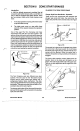
3.
Slide the brake tube, the spring and finally the
brake disk onto the brake cable. Pull the brake
cable sheath down into position at the slot
provided at the bottom of the brake tube and
secure with the cable clamp. See Figure
103.
Cable Clamp Torque:
2.26
N-m
(20
in
Ibs)
NOTE:
The end of the cable sheath will not
fit
past the spring unless the upper end of the cable
clamp is first loosened.
4.
Slip the brake switch into position on the brake
tube and secure with the capscrew and nylon
locknut (locknut on the same side as the switch).
NOTE:
There is no vertical adjustment on
the
switch. To adjust the switching point, adjust
the
brake cable under the control panel. See Figure
105.
Figure
105
5.
To facilitate assembly, tape the control bar to the
handle.
60
Vacu-Power Mower